Preliminary datasheet, Typical performance characteristics (continued), Figure 10. fon – Diodes AP2113 User Manual
Page 8: Logic low level vs. input voltage figure 11. fon, Logic high level vs. input voltage
Preliminary Datasheet
1.6x Linear DC Fan Driver with VOUT Fully on Control AP2113
Mar. 2012 Rev 1. 3 BCD Semiconductor Manufacturing Limited
8
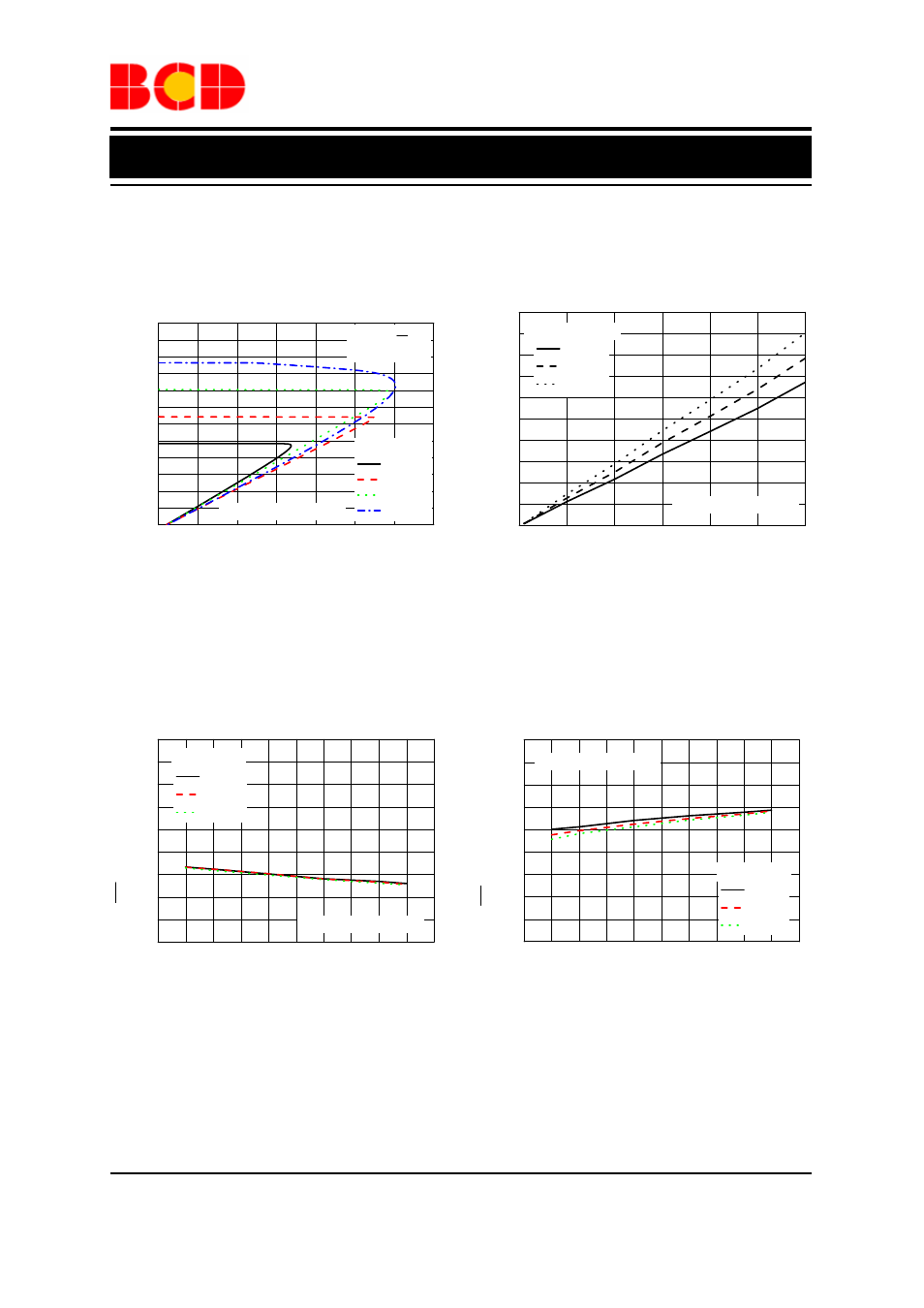
Typical Performance Characteristics (Continued)
Figure 10. FON
________
Logic Low Level vs. Input Voltage Figure 11. FON
________
Logic High Level vs. Input Voltage
0.0
0.1
0.2
0.3
0.4
0.5
0.6
0.00
0.02
0.04
0.06
0.08
0.10
0.12
0.14
0.16
0.18
0.20
Continuous Airflow 10scfm
T
A
=-40
O
C
T
A
=25
O
C
T
A
=85
O
C
Drop
out Vol
ta
ge
(V)
Output Current (A)
Full Speed Mode
Figure 8. Output Voltage vs. Output Current Figure 9. Dropout Voltage vs. Output Current
1
2
3
4
5
6
0.0
0.2
0.4
0.6
0.8
1.0
1.2
1.4
1.6
1.8
Continuous Airflow 10scfm
I
OUT
=0mA
F
O
N L
ogi
c L
o
w
Level
(V)
Input Voltage (V)
T
A
=-40
o
C
T
A
=25
o
C
T
A
=85
o
C
1
2
3
4
5
6
0.0
0.2
0.4
0.6
0.8
1.0
1.2
1.4
1.6
1.8
Continuous Airflow 10scfm
I
OUT
=0mA
Input Voltage (V)
T
A
=-40
o
C
T
A
=25
o
C
T
A
=85
o
C
F
O
N Logi
c
High Level (V)
0.0
0.2
0.4
0.6
0.8
1.0
1.2
1.4
0.0
0.5
1.0
1.5
2.0
2.5
3.0
3.5
4.0
4.5
5.0
5.5
6.0
Continuous Airflow 10scfm
V
IN
=5V, V
FON
=5V
C
IN
=C
OUT
=1
µ
F
O
u
tput Volt
age
(V
)
Output Current (A)
T
C
=25
o
C
V
SET
=1.5V
V
SET
=2.0V
V
SET
=2.5V
V
SET
=3.0V