Two phase hall effect latch with fg output ah211, Data sheet application information – Diodes AH211 User Manual
Page 9
TWO PHASE HALL EFFECT LATCH WITH FG OUTPUT AH211
9
Feb. 2010 Rev. 1. 7
BCD Semiconductor Manufacturing Limited
Data Sheet
Application Information
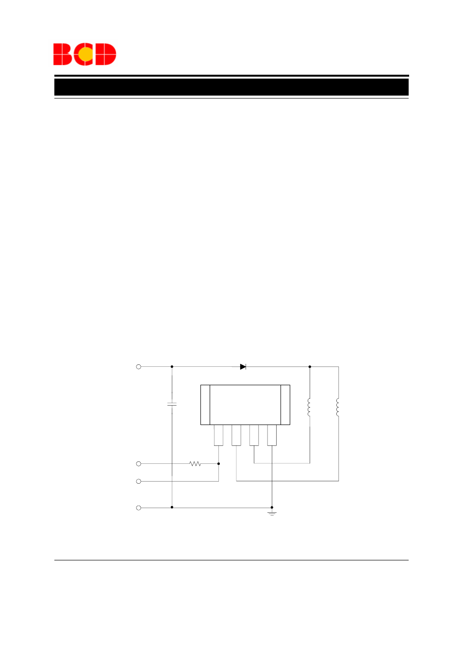
Figure 15 is the typical application circuit for AH211.
Usually, there are three wires for fan connection: the
red is input of power supply; the yellow is the output of
FG; the black is the ground. R1 is an external pull-up
resister for the use of measuring FG signal from fan.
The value of R1 could be decided by the transistor
saturation voltage (V
ON
), sink current (I
FG
), and pull-
up voltage (V
DD
). The calculation formula is:
R1=(V
DD
-V
ON
) / I
FG
For example:
V
DD
=5V for TTL level.
If saturation voltage is 0.6V (IC specification)
I
FG
=20mA (
≤
20mA) , then R1=220
Ω ;
If saturation voltage is 0.1V, I
FG
=1mA (=<20mA) , the
value of R1=4.9k
Ω
According AH211's specification, if V
DD
=5V, R1 must
be larger than 220
Ω.
D1 is the reverse protection diode. If the red and black
wires reversely connected, the current will flow from
the ground via IC and coils L1 and L2 to power supply.
Under such circumstances, the IC and coils are easy to
be burned out. Therefore, the reverse protection diode
D1is necessary. However, D1 will also cause an extra
voltage drop on the supply voltage.
C1 is a capacitor to reduce the ripple noise caused by
the transient of the output stages. The amplitude of the
ripple noise depends on the coil impedance and its
characteristics.
AH211
FG
DO DOB GND
1
2
3
4
COIL1
COIL2
C1
D1
R1 1k
Ω
V
CC
(Red Wire)
V
DD
FG (Yellow Wire)
GND (Black Wire)
Figure 15. AH211 Typical Application Circuit