Ap8800, Application information – Diodes AP8800 User Manual
Page 7
AP8800
Document number: DS31764 Rev. 7 - 2
7 of 13
August 2012
© Diodes Incorporated
AP8800
Application Information
(cont.)
PWM Dimming
A PWM signal with a max resolution of 8bit can be applied to CTRL regulate the output current to a value below the nominal average value set
by resistor R
SET
. PWM dimming gives a wider average LED current variation and is more accurate at lower average LED currents than by
applying DC voltage to the CTRL pin to achieve average LED current dimming.
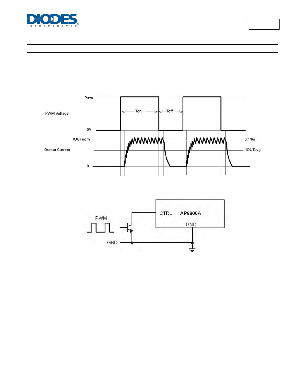
Figure 5 shows the typical PWM response of the AP8800A. An internal filter produces a rump.
Figure 5 Typical PWM Dimming Waveform
The recommended method of driving the CTRL pin and controlling the amplitude of the PWM waveform is to use a small NPN switching
transistor as shown below:
Figure 6 Open Collector PWM Dimming Circuit
This scheme uses the 200k resistor between the ADJ pin and the internal voltage reference as a pull-up resistor for the external transistor eg
MMBT3904.
Soft-Start
An external capacitor from the CTRL pin to ground will provide soft-start delay, by increasing the time taken for the voltage on this pin to rise to
the turn-on threshold and by slowing down the rate of rise of the control voltage at the input of the comparator.
The soft-start time is 0.5ms/nF.