Application information, Al8805 – Diodes AL8805 User Manual
Page 12
AL8805
Document number: DS35030 Rev. 4 - 2
12 of 16
July 2012
© Diodes Incorporated
AL8805
Application Information
(cont.)
Diode Selection
For maximum efficiency and performance, the rectifier (D1) should be a fast low capacitance Schottky diode with low reverse leakage at the
maximum operating voltage and temperature. The Schottky diode also provides better efficiency than silicon PN diodes, due to a combination of
lower forward voltage and reduced recovery time.
It is important to select parts with a peak current rating above the peak coil current and a continuous current rating higher than the maximum
output load current. In particular, it is recommended to have a diode voltage rating at least 15% higher than the operating voltage to ensure safe
operation during the switching and a current rating at least 10% higher than the average diode current. The power rating is verified by
calculating the power loss through the diode.
Schottky diodes, e.g. B240 or B140, with their low forward voltage drop and fast reverse recovery, are the ideal choice for AL8805 applications.
Thermal and Layout Considerations
For continuous conduction mode of operation, the absolute maximum junction temperature must not be exceeded. The maximum power
dissipation depends on several factors: the thermal resistance of the IC package
θ
JA
, PCB layout, airflow surrounding the IC, and difference
between junction and ambient temperature.
The maximum power dissipation can be calculated using the following formula:
P
D(MAX)
= (T
J(MAX)
− T
A
) /
θ
JA
where
T
J(MAX)
is the maximum operating junction temperature,
T
A
is the ambient temperature, and
θ
JA
is the junction to ambient thermal resistance.
The recommended maximum operating junction temperature, T
J
, is +125°C and so maximum ambient temperature is determined by the
AL8805’s junction to ambient thermal resistance,
θ
JA
.
θ
JA
, is layout dependent and the AL8805’s
θ
JA
on a 25 x 25mm single layer PCB with 1oz copper standing in still air is approximately +250°C/W
(+160°C/W on a four-layer PCB).
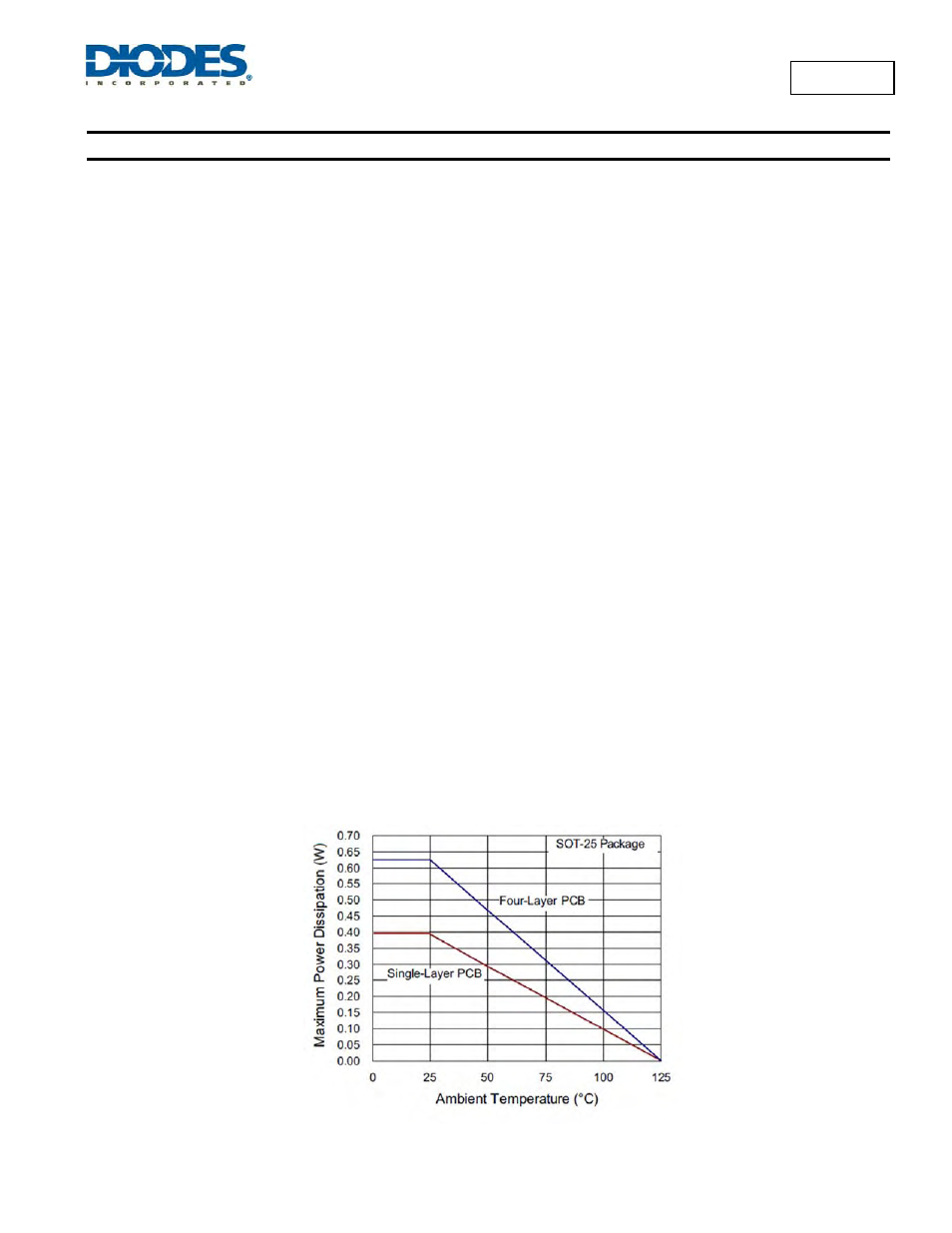
The maximum power dissipation at T
A
= +25°C can be calculated by the following formulas:
P
D(MAX)
= (+125°C
− +25°C) / (250°C/W) = 0.4W for single-layer PCB
P
D(MAX)
= (+125°C
− +25°C) / (160°C/W) = 0.625W for standard four-layer PCB
Figure 34, shows the power derating of the AL8805 on two (one single-layer and four-layer) different 25x25mm PCB with 1oz copper standing in
still air.
Figure 34 Derating Curve for Different PCB