Ap5726 – Diodes AP5726 User Manual
Page 11
AP5726
WHITE LED STEP-UP CONVERTER
AP5726
Document number: DS31845 Rev. 3 - 2
11 of 17
July 2010
© Diodes Incorporated
Applications Information
(Continued)
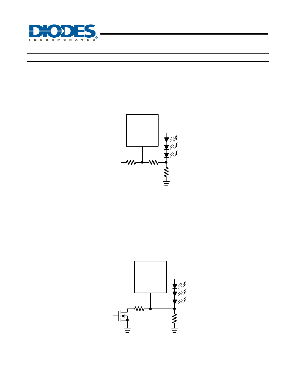
2. Using a DC Voltage
For some applications, the preferred method of brightness control is a variable DC voltage to adjust the
LED current. The dimming control using a DC voltage is shown in Figure 3. As the DC voltage increases, the
voltage drop on R2 increases and the voltage drop on R
SET
decreases. Thus, the LED current decreases. The
selection of R2 and R3 will make the current from the variable DC source much smaller than the LED current and
much larger than the FB pin bias current. For V
DC
range from 0V to 2V, the selection of resistors in Figure 3 gives
dimming control of LED current from 0mA to 20mA.
AP5726
FB
R
SET
15
R2
5k
R3
100k
V
DC
Figure 3. Dimming Control Using a DC Voltage
3. Using a Filtered PWM Signal
The filtered PWM signal can be considered as an adjustable DC voltage. It can be used to replace the variable
DC voltage source in dimming control.
4. Using a Logic Signal
For applications that need to adjust the LED current in discrete steps, a logic signal can be used as shown in
Figure 4. R
SET
sets the minimum LED current (when the NMOS is off). R
SET
sets how much the LED current
increases when the NMOS is turned on.
AP5726
FB
R
SET
R
INC
Logic
Signal
Figure 4.
Dimming Control Using a Logic Signal