Ap5726 – Diodes AP5726 User Manual
Page 10
AP5726
WHITE LED STEP-UP CONVERTER
AP5726
Document number: DS31845 Rev. 3 - 2
10 of 17
July 2010
© Diodes Incorporated
Applications Information
(Continued)
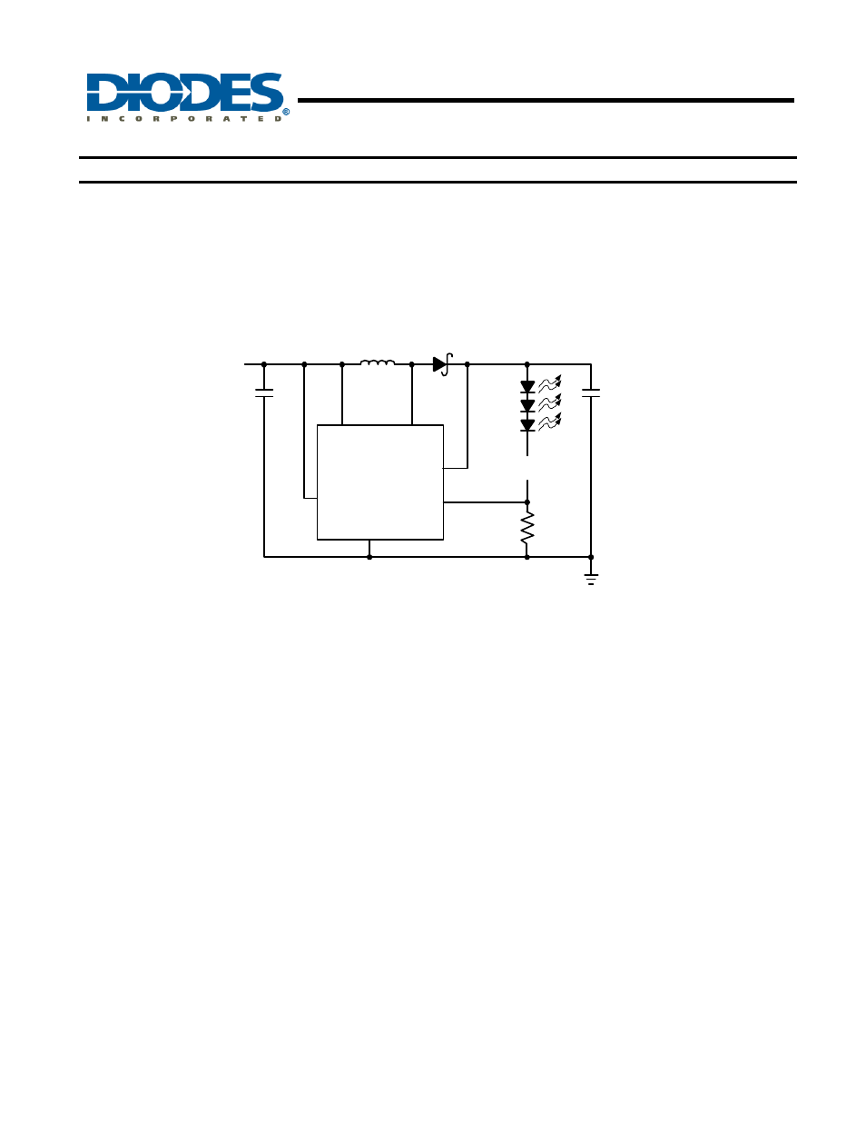
Open-Circuit Protection
In the cases of output open circuit, when the LEDs are disconnected from the circuit or the LEDs fail, the
feedback voltage will be zero. The AP5726 will then switch at a high duty cycle resulting in a high output voltage,
which may cause the SW and OVP pin voltage to exceed the voltage rating of these pins. The OVP pin monitors
the output voltage. If the output voltage reaches the over voltage protection threshold at the OVP pin (Figure 2),
the over voltage protection is activated and SW pin stops switching.
V
IN
SW
EN
GND
FB
AP5726
C
OUT
1uF
R
SET
15
L1
22uH
D1
V
IN
C
IN
1uF
OVP
x
x
Figure 2. LED Driver with Open-Circuit Protection
Dimming Control
There are four different types of dimming control circuits:
1. Using a PWM Signal to EN Pin
With the PWM signal applied to the EN pin, the AP5726 is turned on or off by the PWM signal. The LEDs operate
at either zero or full current. The average LED current increases proportionally with the duty cycle of the PWM
signal. A 0% duty cycle will turn off the AP5726 and corresponds to zero LED current. A 100% duty cycle
corresponds to full current. The typical frequency range of the PWM signal is below 2kHz.