Ap1684, Electrical characteristics – Diodes AP1684 User Manual
Page 4
AP1684
Document number: DS36547 Rev.
3 - 2
4 of 13
February 2014
© Diodes Incorporated
AP1684
A Product Line of
Diodes Incorporated
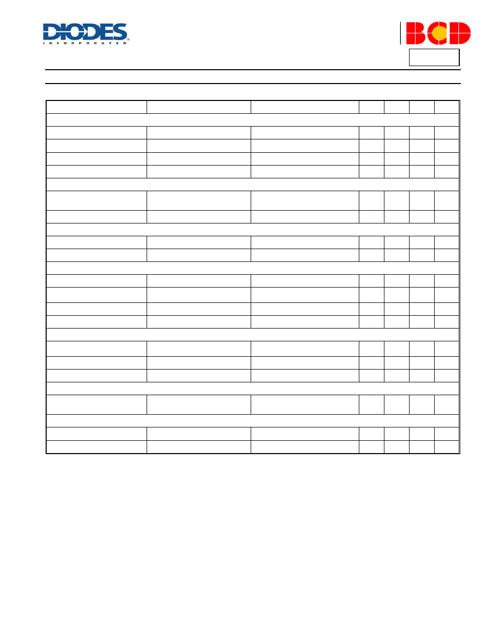
Electrical Characteristics
(@T
A
= +25°C, unless otherwise specified.)
Symbol
Parameter
Conditions
Min
Typ
Max
Unit
UVLO Section
V
TH
(ST)
Start-up Threshold
–
18
19
20
V
V
OPR
(Min)
Minimum Operating Voltage
After turn on
5.5
6.5
7.5
V
V
CC_OVP
VCC OVP Voltage
–
30
32
34
V
–
VCC Delatch Voltage (Note 5)
–
3
4
5
V
Standby Current Section
I
ST
Start-up Current
V
CC
= V
TH
(ST)-0.5V,
Before start up
–
–
20
μA
I
CC
(OPR)
Operating Current
Static
–
900
1300
μA
Drive Output Section
I
OUT
Output Current (Note 5)
V
CS_PEAK
= 1V
–
–
60
mA
V
OS
UVLO Saturation Voltage
V
CC
= 0 to V
CC-ON
, I
SINK
= 10mA
–
–
1.1
V
Current Sense Section
V
CS_REF
Current Sense Reference
–
–
1
–
V
V
CS_CLAMP
Current Sense Reference
Clamp
–
1.2
1.4
–
V
t
ONP_MIN
Minimum t
ONP
–
700
–
1000
ns
t
D(H-L)
Delay to Output (Note 5)
–
50
150
250
ns
Feedback Input Section
I
FB
Feedback Pin Input Leakage
Current
V
FB
= 2V
–
–
4
μA
V
FB_CV
FB CV Threshold
–
3.8
4
4.2
V
V
FB_OVP
FB OVP Threshold
–
4.5
6
7.5
V
Output Current
–
System Output Current on Final
Test Board
–
–
–
±2
%
Over Temperature Protection Section
–
Shutdown Temperature (Note 5)
–
+150
–
–
°C
–
Temperature Hysteresis (Note 5)
–
–
+20
–
°C
Note 5: These parameters, although guaranteed by design, are not 100% tested in production.