Ap130, 300ma low dropout (ldo) linear regulator, Electrical characteristics – Diodes AP130 User Manual
Page 4
AP130
300mA LOW DROPOUT (LDO) LINEAR REGULATOR
AP130
Document number: DS31027 Rev. 8 - 2
4 of 11
December 2011
© Diodes Incorporated
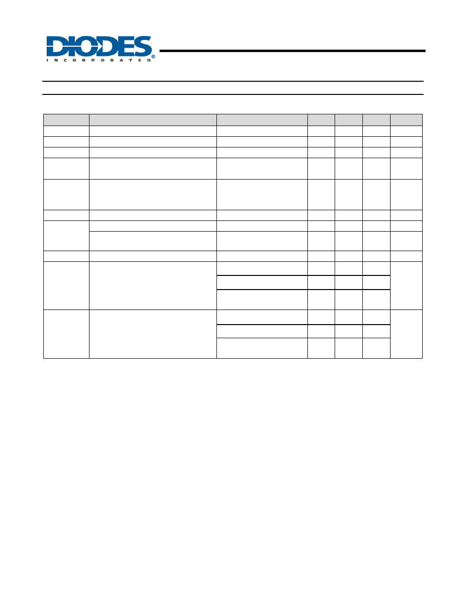
Electrical Characteristics
T
A
= 25ºC, C
IN
= 1µF, C
OUT
= 10µF, unless otherwise specified.
Symbol
Parameter
Conditions
Min
Typ.
Max
Unit
V
DROP
Dropout Voltage (Note 2)
I
L
= 300mA
- 400
500 mV
I
LIMIT
Current Limit (Note 3)
V
IN
= 5V, V
OUT
= 0V
350 450 -
mA
I
short
Short Circuit Current
V
OUT
< 1.05V
- 150
300 mA
ΔV
LINE
Line Regulation
I
OUT
= 1mA,
V
IN
= (V
OUT
+1V) to 5.5V
- 0.1
0.3 %/V
PSRR Ripple
Rejection
F = 100Hz,
C
IN
= 1
μF, C
O
= 10uF,
I
L
= 100mA
- 58 - dB
ΔV
LOAD
Load Regulation (Note 4)
I
L
= 1~300mA, V
IN
= 5V
- 30 40 mV
ΔV
OUT
Output Voltage Accuracy
I
L
= 1mA, V
IN
= 5V
-2 - +2 %
Output Voltage Temperature Coefficient
(Note 5)
-
50
150
PPM/ºC
I
Q
Quiescent Current
I
L
= 0mA, V
IN
= 5V
- 50
100
μA
θ
JA
Thermal Resistance Junction-to-Ambient
SC59/SC59R (Note 6)
-
250
-
ºC/W
SOT23 (Note 7)
-
200
-
SOT89-3L/SOT89R-3L
(Note 8)
-
100
-
θ
JC
Thermal Resistance Junction-to-Case
SC59/SC59R (Note 6)
-
79
-
ºC/W
SOT23 (Note 7)
-
43
-
SOT89-3L/SOT89R-3L
(Note 8)
-
23
-
Notes:
2. Dropout voltage is defined as the input to output differential voltage. Dropout is measured at constant junction temperature by using pulsed on time,
and the criterion is V
OUT
inside target value ±2%. This test is skipped at the condition of V
IN
<3V.
3. Current limit is measured at constant junction temperature by using pulsed testing with a low ON time.
4. Regulation is measured at constant junction temperature by using pulsed testing with a low ON time.
5. Guaranteed by design.
6. Test condition for SC59/SC59R: Devices mounted on FR-4 PC board, 1
*
MRP, 2oz copper, single sided, calibrate at T
J
=125ºC, T
A
=25ºC, with
minimum recommended pad layout.
7. Test condition for SOT23: Devices mounted on FR-4 PC board, 1
*
MRP, calibrate at T
J
=85ºC, T
A
=29ºC.
8. Test condition for SOT89-3L/SOT89R-3L: No Heat Sink, no air flow.