Ap2281, Typical performance characteristics – Diodes AP2281 User Manual
Page 6
AP2281
Document number: DS31359 Rev. 7 - 2
6 of 11
November 2013
© Diodes Incorporated
AP2281
Typical Performance Characteristics
(cont.)
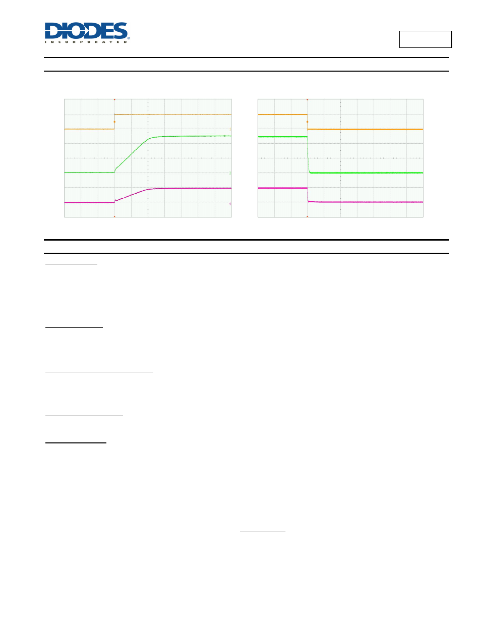
AP2281-3 Turn-On
(V
IN
= 5V, R
L
= 10Ω)
Time (50μs/div)
AP2281-3 Turn-Off
(V
IN
= 5V, R
L
=10Ω)
Time (50μs/div)
Application Notes
Input Capacitor
A 1μF capacitor is recommended to connect between IN and GND pins to decouple input power supply glitch and noise. The input capacitor has
no specific type or ESR (Equivalent Series Resistance) requirement. However, for higher current application, ceramic capacitors are
recommended due to their capability to withstand input current surges from low impedance sources, such as batteries in portable applications.
This input capacitor must be located as close as possible to the device to assure input stability and less noise. For PCB layout, a wide copper
trace is required for both IN and GND
.
Output Capacitor
A 0.1μF capacitor is recommended to connect between OUT and GND pins to stabilize and accommodate load transient condition. The output
capacitor has no specific type or ESR requirement. The amount of the capacitance may be increased without limit. For PCB layout, the output
capacitor must be placed as close as possible to OUT and GND pins, and keep the traces as short as possible.
ENABLE/SHUTDOWN Operation
The AP2281 is turned on by setting the EN pin high, and is turned off by pulling it low. To ensure proper operation, the signal source used to
drive the EN pin must be able to swing above and below the specified turn-on/off voltage thresholds listed in the Electrical Characteristics section
under V
IL
and V
IH
.
DISCHARGE Operation
The AP2281-3 offers discharge option that helps to discharge the output charge when disabled.
Power Dissipation
The device power dissipation and proper sizing of the thermal plane is critical to avoid thermal shutdown and ensure reliable operation. Power
dissipation of the device depends on input voltage and load conditions and can be calculated by:
DSON
2
OUT
D
xR
I
P
(1)
However, the maximum power dissipation that can be handled by the device depends on the maximum junction to ambient thermal resistance,
maximum ambient temperature, and maximum device junction temperature, which can be approximated by the equation below:
JA
A
A
D
)
T
C
125
(
)
T
(max@
P
(2)
For example at V
IN
= 5V, the typical R
DSON
= 80mΩ. For I
OUT
= 2A, the maximum power dissipation calculated using equation (1) is P
D
= 0.32W.
Based on SOT26 θ
JA
= 153°C/W and equation (2), the calculated junction temperature rise from ambient is approximately 49°C. Since the
maximum junction temperature is 125°C, the operating ambient temperature must be kept below 76°C to safely operate the device.
VEN (5V/div)
VOUT (2V/div)
IIN (500mA/div)
VEN (5V/div)
VOUT (2V/div)
IIN (500mA/div)