Ap6507, New prod uc t absolute maximum ratings, Thermal resistance – Diodes AP6507 User Manual
Page 3: Recommended operating conditions
AP6507
500 kHz 18V 3A SYNCHRONOUS DC/DC BUCK CONVERTER
AP6507
Document number: DS33435 Rev. 3 - 2
3 of 13
October 2011
© Diodes Incorporated
NEW PROD
UC
T
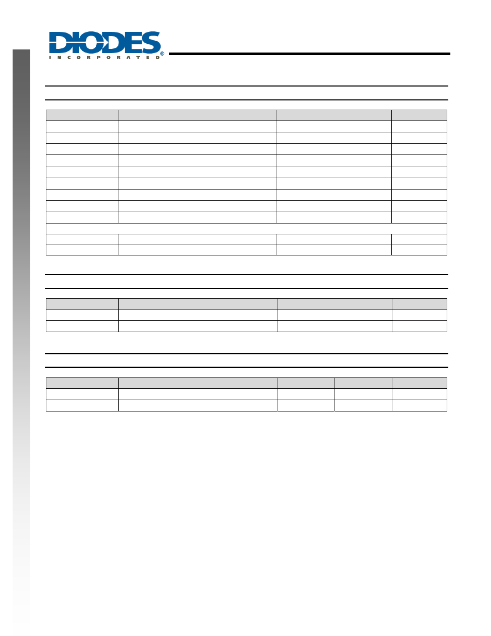
Absolute Maximum Ratings
(T
A
= 25
°C)
Symbol
Parameter
Rating
Unit
V
IN
Supply Voltage
19
V
V
SW
Switch Node Voltage
-0.3 to 20
V
V
BS
Bootstrap Voltage
V
SW
+ 6
V
V
FB
Feedback Voltage
–0.3 to +6
V
V
EN
Enable/UVLO Voltage
–0.3 to +6
V
V
COMP
Comp Voltage
–0.3 to +6
V
T
ST
Storage Temperature
-65 to +150
°C
T
J
Junction Temperature
+150
°C
T
L
Lead Temperature
+260
°C
ESD Susceptibility (Note 3)
HBM Human
Body
Model
3
kV
MM Machine
Model
300
V
Thermal Resistance
(Note 4)
Symbol
Parameter
Rating
Unit
θ
JA
Junction to Ambient
56
°C/W
θ
JC
Junction to Case
16
°C/W
Recommended Operating Conditions
(Note 5)
Symbol
Parameter
Min
Max
Unit
V
IN
Supply Voltage
4.5
18 V
T
A
Operating Ambient Temperature Range
-40
+85 °C
Notes:
2. Stresses greater than the 'Absolute Maximum Ratings' specified above, may cause permanent damage to the device. These are stress ratings
only; functional operation of the device at these or any other conditions exceeding those indicated in this specification is not implied. Device
reliability may be affected by exposure to absolute maximum rating conditions for extended periods of time.
3. Semiconductor devices are ESD sensitive and may be damaged by exposure to ESD events. Suitable ESD precautions should be taken when
handling and transporting these device.
4. Test condition for SO-8EP: Device mounted on 2"*2" FR-4 substrate PC board, 2oz copper, with minimum recommended pad on top layer and
thermal vias to bottom layer ground plane.
5. The device function is not guaranteed outside of the recommended operating conditions.