Ap1534, Pwm control 2a step-down converter, Pin descriptions – Diodes AP1534 User Manual
Page 2: Functional block diagram, Absolute maximum ratings
AP1534
PWM CONTROL 2A STEP-DOWN CONVERTER
AP1534
Document number: DS31314 Rev. 6 - 2
2 of 9
April 2011
© Diodes Incorporated
Pin Descriptions
Pin Name
Pin No.
Description
FB
1
Feedback pin
EN
2
Power-off pin
H: Normal operation
(Step-down operation)
L: Step-down operation stopped
(All circuits deactivated)
OCSET
3
Add an external resistor to set max output current
V
CC
4
IC power supply pin
Output 5,
6
Switch Pin. Connect external inductor/diode here.
Minimize trace area at this pin to reduce EMI
V
SS
7, 8
GND Pin
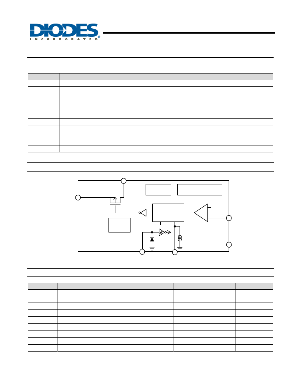
Functional Block Diagram
Oscillation
Circuit
Reference Voltage
Source
PWM-Switched
Control Circuit
+
-
Vss
V
EN
EN
100uA
OCSET
FB
Vcc
Thermal
Shutdown
Output
Absolute Maximum Ratings
Symbol
Parameter
Rating
Unit
ESD HBM
Human Body Model ESD Protection
4.5
KV
ESD MM
Machine Model ESD Protection
150
V
V
CC
VCC Pin Voltage
V
SS
- 0.3 to V
SS
+ 20
V
V
FB
Feedback Pin Voltage
V
SS
- 0.3 to V
CC
V
V
EN
EN Pin Voltage
V
SS
- 0.3 to V
IN
V
V
OUT
Switch Pin Voltage
V
SS
- 1.0 to V
IN
V
P
D
Power Dissipation
Internally limited
mW
T
J
Operating Junction Temperature Range
-40 to +125
o
C
T
ST
Storage Temperature Range
-65 to +150
o
C
Caution:
The absolute maximum ratings are rated values exceeding which the product could suffer physical damage.
These values must therefore not be exceeded under any conditions.