Ap1501, Recommended operating conditions, Electrical characteristics – Diodes AP1501 User Manual
Page 4: 150khz, 3a pwm buck dc/dc converter
AP1501
150KHz, 3A PWM BUCK DC/DC CONVERTER
AP1501 Rev. 11
4 of 12
JANUARY 2009
www.diodes.com
©
Diodes Incorporated
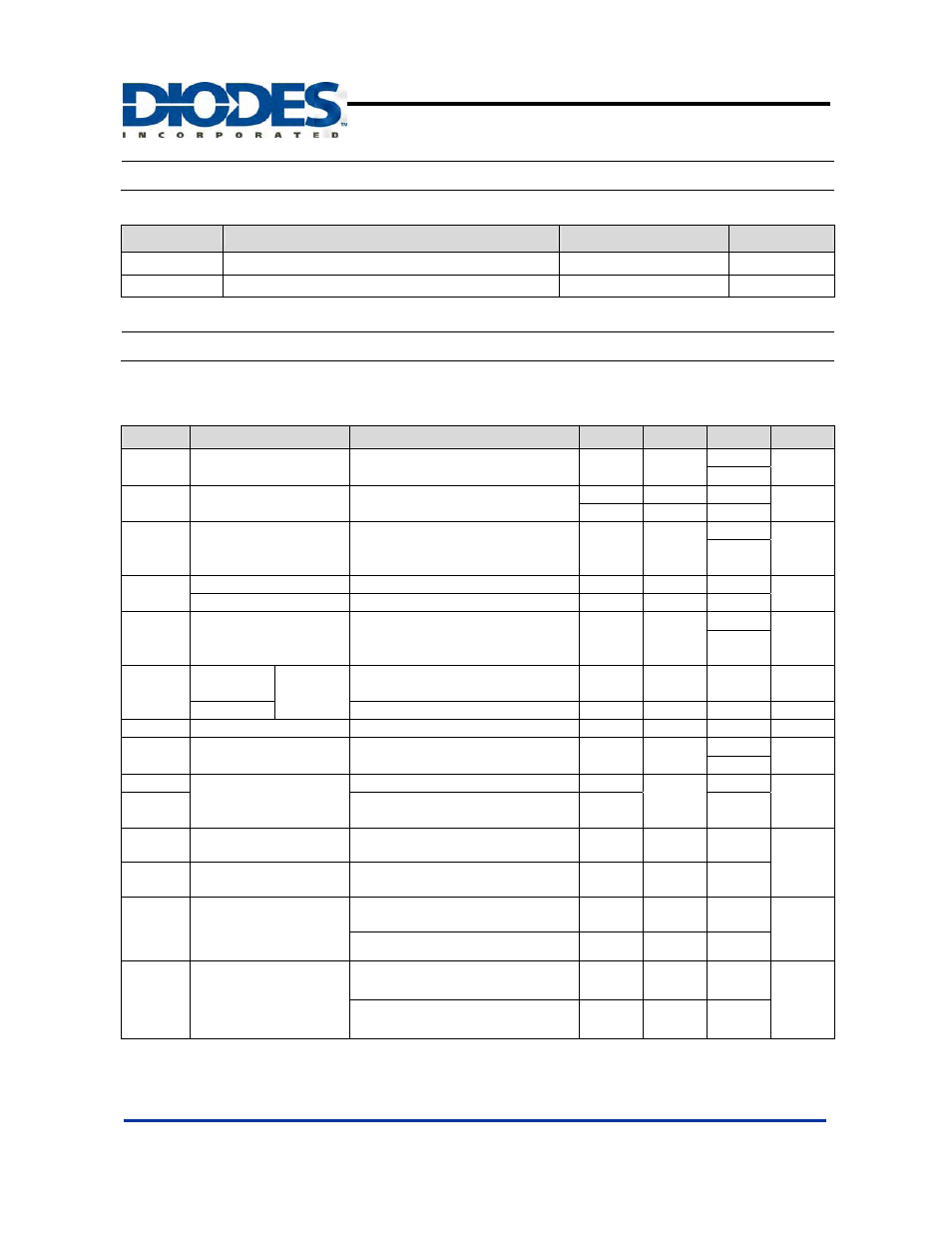
Recommended Operating Conditions
Symbol
Parameter
Rating
Units
V
OP
Operating Voltage
4.5 to 40
V
T
A
Operating Ambient Temperature
-20 to 85
o
C
Electrical Characteristics
(All Output Voltage Versions)
Unless otherwise specified, V
IN
= 12V for 3.3V, 5V, adjustable version and V
IN
= 24V for the 12V version. I
LOAD
= 0.5A
Specifications with boldface type are for full operating temperature range, the other type are for T
J
= 25ºC.
Symbol
Parameter
Conditions
Min
Typ.
Max
Unit
I
FB
Feedback
Bias
Current
V
FB
= 1.3V
(Adjustable version only)
40
60
nA
100
F
OSC
Oscillator
Frequency
127 150 173
KHZ
110 173
V
SAT
Saturation
Voltage
I
OUT
= 3A
No outside circuit
V
FB
= 0V force driver on
1.3
1.4
V
1.5
DC
Max. Duty Cycle(ON)
V
FB
= 0V force driver on
100
%
Min. Duty cycle(OFF)
V
FB
= 12V force driver off
0
I
CL
Current
Limit
Peak current
no outside circuit
V
FB
= 0V force driver on
3.6 4.0
5.5
A
6.5
I
L
Output = 0
Output
Leakage
Current
No outside circuit
V
FB
= 12V force driver off (Note 3)
200
uA
Output = -1
V
IN
= 40V
2
60
mA
I
Q
Quiescent
Current V
FB
= 12V force driver off
5 10
mA
I
STBY
Standby Quiescent
Current
ON/OFF pin = 5V
V
IN
= 40V
150
250
uA
350
V
IL
ON/OFF pin Logic Input
Threshold Voltage
Low (regulator ON)
1.3
0.6
V
V
IH
High (regulator OFF)
2.0
I
H
ON/OFF Pin Logic
Input Current
V
LOGIC
= 2.5V (OFF)
15
25
uA
I
L
ON/OFF Pin Input
Current
V
LOGIC
= 0.5V (ON)
0.02
5
θ
JA
Thermal Resistance
unction to Ambient
TO263-5L (Note 4)
37
o
C/W
TO220-5L(R) (Note 4)
31
θ
JC
Thermal Resistance
Junction to Case
TO263-5L (Note 4)
6
o
C/W
TO220-5L(R) (Note 4)
5
Notes: 3. Feedback pin removed from output and connected to 0V to force the output transistor switch ON. Feedback pin removed from output and
connected to 12V for the 3.3V, 5V, and the ADJ. version, and 15V for the 12V version, to force the output transistor switch OFF.
4. Test condition: Device mounted with copper area of approximately 3 in
2
,1oz,
no air flow.