Ap3107z, Typical applications circuit, Pin descriptions – Diodes AP3107Z User Manual
Page 2
AP3107Z
Document number: DS36677 Rev.
2 - 1
2 of 11
www.diodes.com
November 2013
© Diodes Incorporated
AP3107Z
A Product Line of
Diodes Incorporated
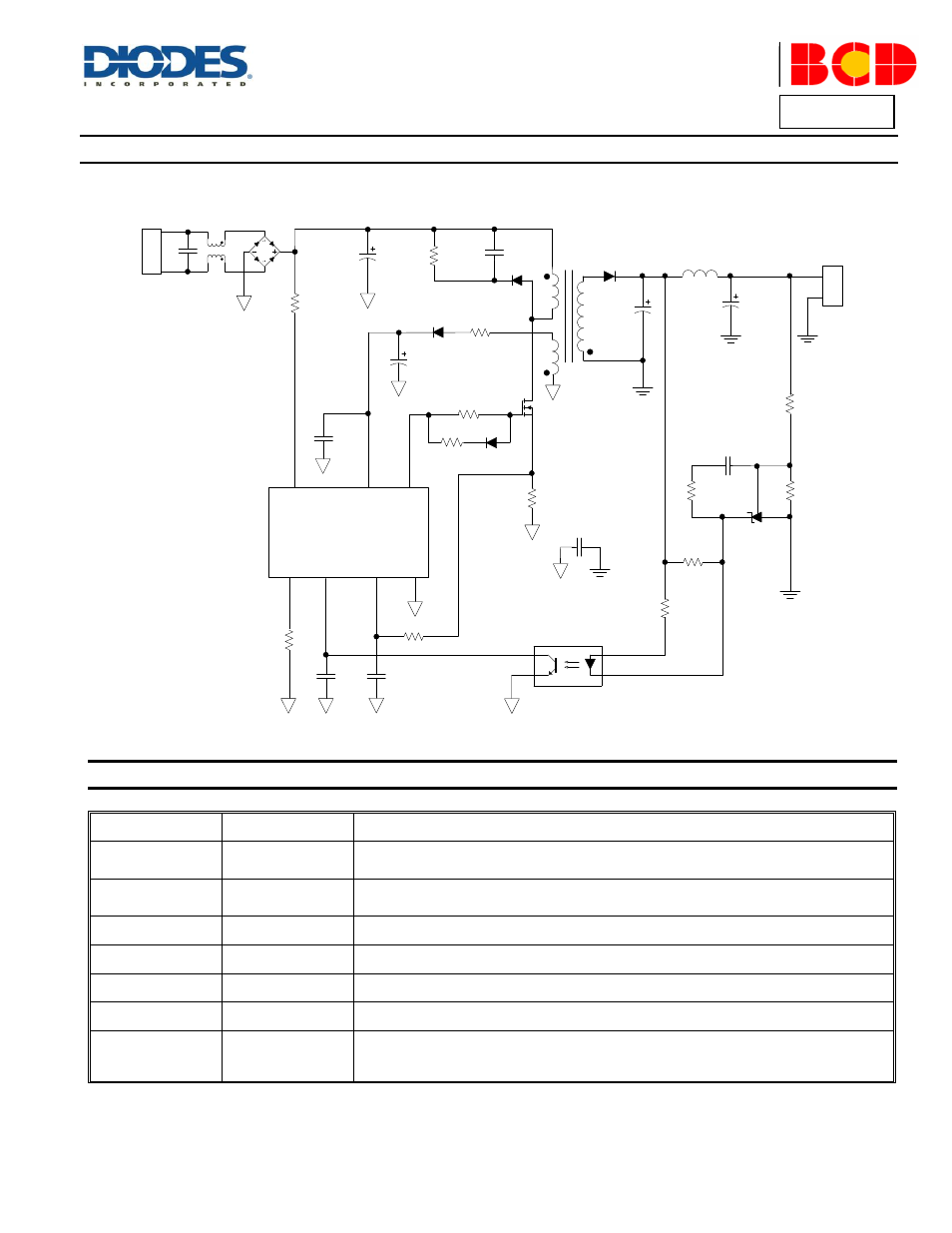
Typical Applications Circuit
Pin Descriptions
Pin Number
Pin Name
Function
1
BNO
Brownout Protection Pin. Connected to GND by a resistor to set the brownout level. This pin is
shortened to the ground to set the maximum brownout voltage
2
FB
Voltage Feedback Pin., Connecting it with an opto-coupler to close the control loop can
achieve system regulation
3
SENSE
Current Sense Pin. Connect it to sense the MOSFET current
4
GND
Ground
5
GATE
Gate drive output to drive the external MOSFET
6
VCC
Supply Voltage Pin
7
HV
Connect this pin to the positive terminal of bulk capacitor to provide start-up current for the
controller. When VCC voltage reaches UVLO (on), this HV loop will be turned off to save the
power loss of the start-up circuit
R10
5.1k
C10 0.1
F
C4
R9
4.7k
R8
20k
C3
2nF
R4
R12
620
R7
0.5
Q1
7N60
BD1
R2
100k
V
OUT
J1
C2
100
F
1
2
4
3
U2
U3 AZ431
D2
FR107
R5
510
R1
20k
C9
470
F
L2 5
H
D3
C8
1000
F
T
HV
BNO
GATE
VCC
FB
GND
U1 AP3107Z
22
F
C1
D1
C7
C6
C5
SENSE
2k
R11
0.1
F
470pF
R3
R6
MBR20H100C
L1
J2
C11
D4
R13