Preliminary datasheet, High voltage green mode pwm controller ap3106, Pin configuration – Diodes AP3106 User Manual
Page 2: Pin description
Preliminary Datasheet
HIGH VOLTAGE GREEN MODE PWM CONTROLLER AP3106
Sep. 2011 Rev. 1. 0 BCD Semiconductor Manufacturing Limited
2
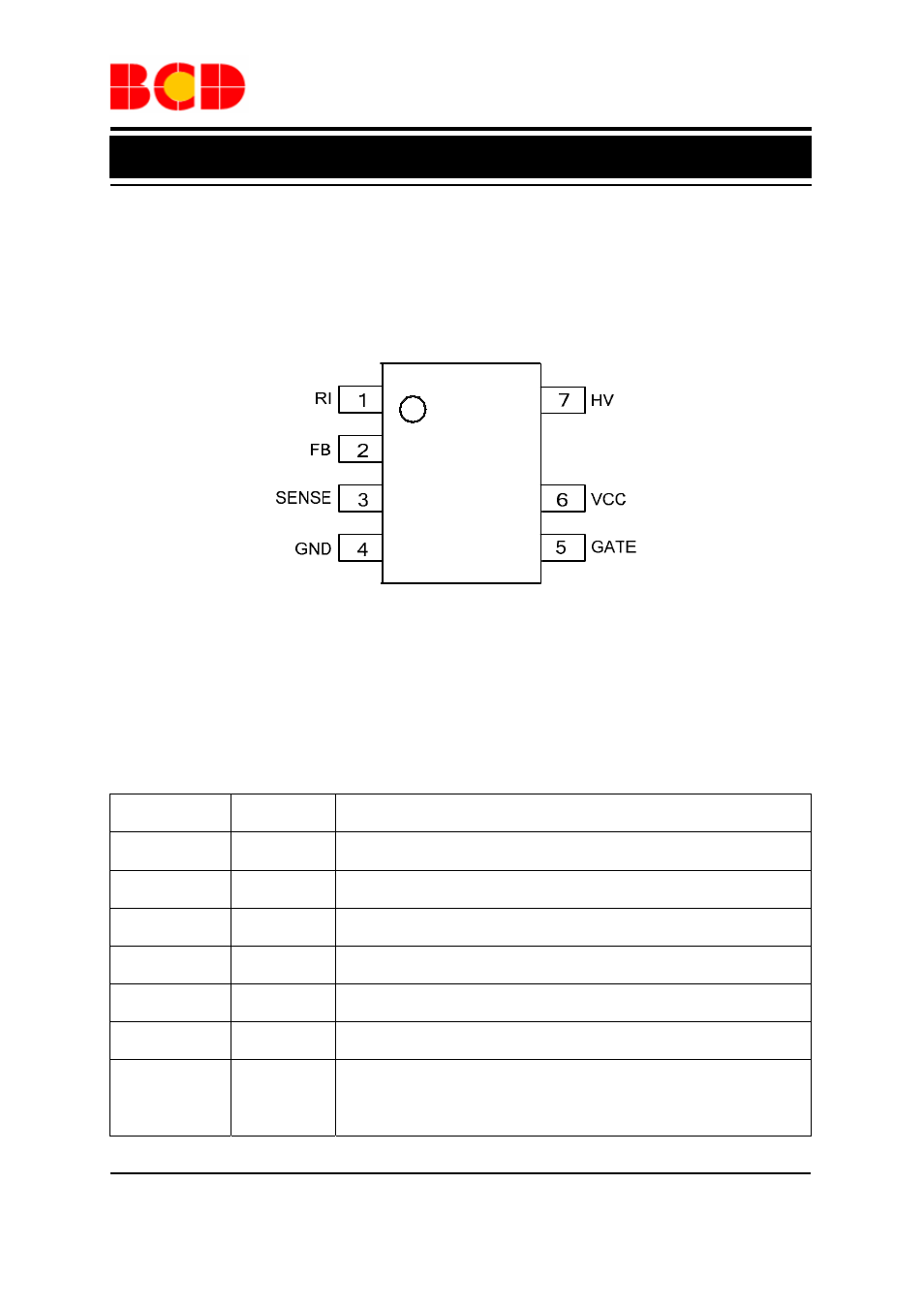
Pin Configuration
M Package
(SOIC-7)
Figure 2. Pin Configuration of AP3106 (Top View)
Pin Description
Pin Number
Pin Name
Function
1
RI
Set the bias current to determine the normal switching frequency
2 FB
Voltage feedback pin. By connecting an opto-coupler to close the
control loop, it can achieve the system regulation
3
SENSE
Current sense pin. Connect it to sense the MOSFET current
4 GND
Ground
5
GATE
Gate drive output to drive the external MOSFET
6
VCC
Supply voltage pin
7 HV
Connect this pin to positive terminal of bulk capacitor to provide the
startup current for the controller. When VCC voltage reachs UVLO
(on), this HV loop will be turned off to save the power loss of the
startup circuit
- PDS3200 (5 pages)
- PDS340 (5 pages)
- PDS340Q (5 pages)
- PDS360 (5 pages)
- PDS360Q (5 pages)
- PDS4150 (4 pages)
- PDS3100Q (5 pages)
- PDS3100 (5 pages)
- PDS1240CTL (5 pages)
- PDS1045 (5 pages)
- PDS1040L (5 pages)
- PDS1040CTL (5 pages)
- PDS1040 (5 pages)
- PD3S230L (5 pages)
- PD3S230H (3 pages)
- PDS5100Q (5 pages)
- PDS835L (5 pages)
- PDS760 (5 pages)
- PDS560 (5 pages)
- PDS540 (5 pages)
- PDS5100H (5 pages)
- PDS5100 (5 pages)
- PDS4200H (6 pages)
- SBL3060CTP (4 pages)
- SBL30L30CT (3 pages)
- SBL3045CTP (4 pages)
- SBL3040CTP (4 pages)
- SBL2060CTP (4 pages)
- SBL2030CT - SBL2060CT (3 pages)
- SBL2045CTP (4 pages)
- SBL1060CTP (4 pages)
- SBL1040CTP (4 pages)
- SBG3030CT - SBG3045CT (5 pages)
- SB520 - SB560 (3 pages)
- SB370 - SB3100 (3 pages)
- SB320 - SB360 (3 pages)
- SBR10U100CT (5 pages)
- SBR10U150CT (5 pages)
- SBR10A45SP5 (5 pages)
- SBR1060CT (5 pages)
- SBR1045SP5 (5 pages)
- SBR1045SD1 (4 pages)
- SBR1045D1 (5 pages)
- SBR1045CTL (4 pages)
- SBR1040CT (5 pages)