Diodes AP3988/89/90 User Manual
Page 7
AP3988/89/90
Document number: DS36722 Rev. 3 - 2
7 of 13
www.diodes.com
March 2014
© Diodes Incorporated
AP3988/89/90
A Product Line of
Diodes Incorporated
N
E
W
P
R
O
D
U
C
T
Operation Description
(Cont.)
Constant Primary Peak Current
The primary i
p
(t) current is sensed by a current sense resistor R
CS
as shown in Figure 1.
The current rises up linearly at a rate of:
M
b
L
t
V
dt
t
di
)
(
)
(
ulk
p
………
(1)
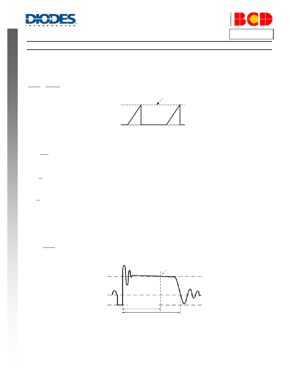
i
p
(t)
0A
See equation 2
I
PK
Figure 2. Primary Current Waveform
As illustrated in Figure 2, when the current i
p
(t)
rises up to I
PK
, the switch Q1 turns off. The constant peak current is given by:
CS
CS
PK
R
V
I
………
(2)
The energy stored in the magnetizing inductance L
M
each cycle is therefore:
2
g
2
1
PK
M
I
L
E
………
(3)
So the power transferring from input to output is given by:
SW
PK
M
f
I
L
P
2
2
1
………
(4)
Where f
SW
is the switching frequency. When the peak current I
PK
is constant, the output power depends on the switching frequency f
SW
.
Constant Voltage Operation
The AP3988/89/90 captures the auxiliary winding feedback voltage at FB pin and operates in constant-voltage (CV) mode to regulate the output
voltage. Assuming the secondary winding is master, the auxiliary winding is slave during the D1 on-time. The auxiliary voltage is given by:
d
S
AUX
AUX
V
V
N
N
V
O
………
(5)
Where V
d
is the diode forward drop voltage, N
AUX
is the turns of auxiliary winding, and N
S
is the turns of secondary winding.
See equation 5
V
AUX
0V
Portion of T
ons
T
ons
Figure 3. Auxiliary Voltage Waveform
The output voltage is different from the secondary voltage in a diode forward drop voltage V
d
which depends on the current. If the secondary
voltage is always detected at a constant secondary current, the difference between the output voltage and the secondary voltage will be a fixed V
d
.
The voltage detection point is portion of T
ons
after D1 is turned on. The CV loop control function of AP3988/89/90 then generates a D1 off-time to
regulate the output voltage.