Diodes DCX (xxxx) K User Manual
Page 2
DCX (xxxx) K
Document number: DS30350 Rev. 6 - 2
2 of 12
www.diodes.com
October 2008
© Diodes Incorporated
DCX (xxxx) K
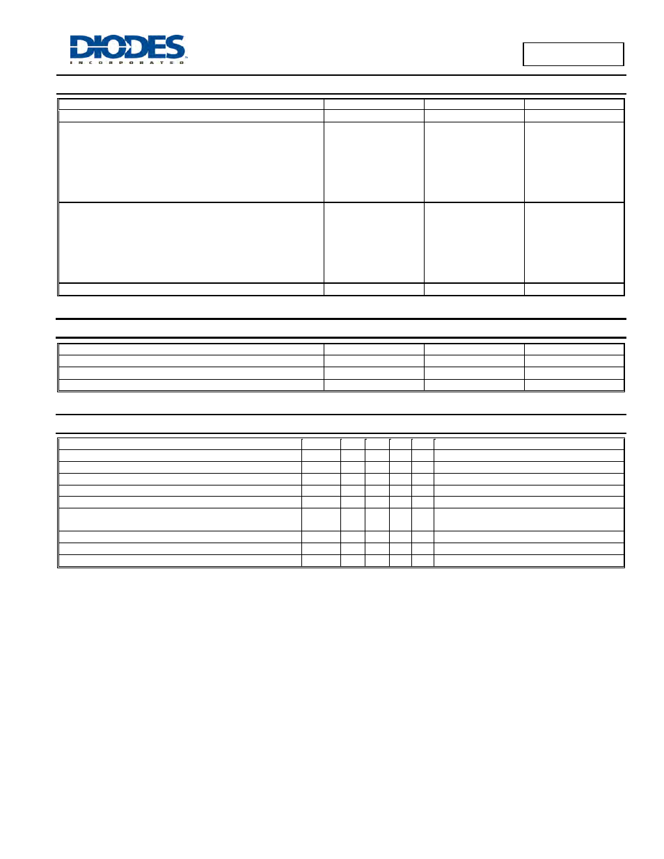
Maximum Ratings PNP Section
@T
A
= 25°C unless otherwise specified
Characteristic
Symbol
Value
Unit
Supply Voltage
V
CC
50
V
Input Voltage
DCX124EK
DCX144EK
DCX114YK
DCX123JK
DCX114EK
DCX115EK
DCX143TK
DCX114TK
V
IN
+10 to –40
+10 to –40
+6 to –40
+5 to –12
+10 to –40
+10 to –40
+5V max
+5V max
V
Output Current
DCX124EK
DCX144EK
DCX114YK
DCX123JK
DCX114EK
DCX115EK
DCX143TK
DCX114TK
I
O
-30
-30
-70
-100
-50
-20
-100
-100
mA
Output Current
All
I
C(MAX)
-100
mA
Thermal Characteristics PNP Section
Characteristic
Symbol
Value
Unit
Power Dissipation (Total) (Note 4)
P
D
300
mW
Thermal Resistance, Junction to Ambient Air (Note 4)
R
θJA
833
°C/W
Operating and Storage Temperature Range
T
J
, T
STG
-55 to +150
°C
Electrical Characteristics NPN Section
@T
A
= 25°C unless otherwise specified
Characteristic (DDC143TK & DDC114TK only)
Symbol
Min
Typ Max Unit
Test Condition
Collector-Base Breakdown Voltage
BV
CBO
50
⎯
⎯
V
I
C
= 50
μA
Collector-Emitter Breakdown Voltage
BV
CEO
50
⎯
⎯
V
I
C
= 1mA
Emitter-Base Breakdown Voltage
BV
EBO
5
⎯
−−
V
I
E
= 50
μA
Collector Cutoff Current
I
CBO
⎯
⎯ 0.5
μA V
CB
= 50V
Emitter Cutoff Current
I
EBO
⎯
⎯ 0.5
μA V
EB
= 4V
Collector-Emitter Saturation Voltage
V
CE(SAT)
⎯
⎯ 0.3
V
I
C
/I
B
= 2.5mA / 0.25mA – DCX143TK
I
C
/I
B
= 1mA / 0.1mA – DCX114TK
DC Current Transfer Ratio
h
FE
100
250
600
⎯ I
C
= 1mA, V
CE
= 5V
Input Resistor (R
1
) Tolerance
ΔR
1
-30
⎯ +30
%
⎯
Gain-Bandwidth Product*
f
T
⎯ 250
⎯ MHz V
CE
= 10V, I
E
= -5mA, f = 100MHz
* Transistor - For Reference Only