Zlnb2013 – Diodes ZLNB2013 User Manual
Page 5
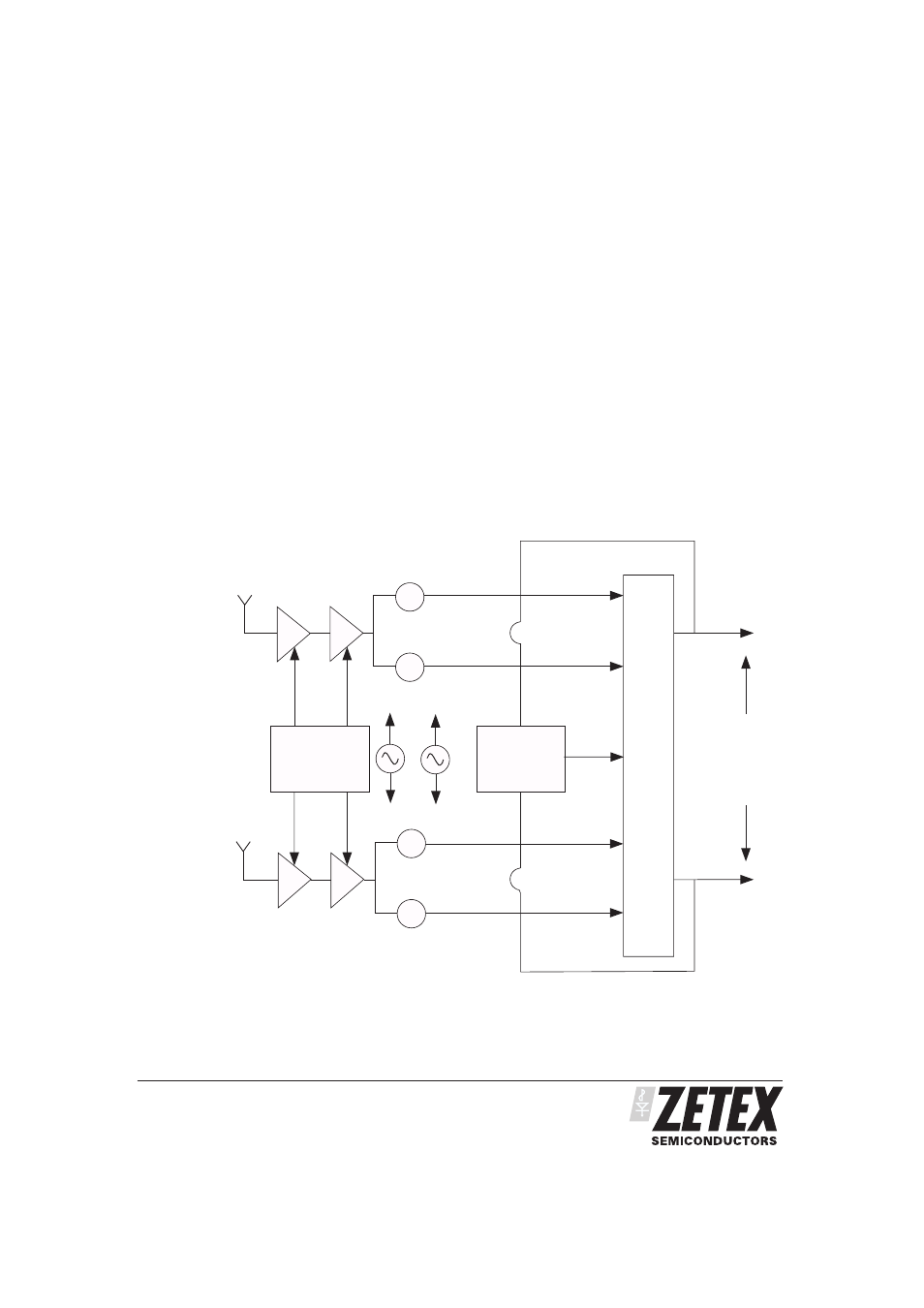
The following diagram shows a typical block diagram
for a twin universal LNB design. The ZLNB2013 device
provides the two polarity and two tone
switches
required to decode the two independent receiver feeds.
The device is also able to detect the absence of a
revceiver connection to either port of the LNB
providing all outputs to go high hence disabling of the
port. This allows the avoidance of unwanted signal
reflections from an unterminated down feed cable.
Additionally the front end bias requirements of the LNB
are provided by the ZNBG fixed bias range offering a
very efficient and cost effective solution
ISSUE 1 - AUGUST 2005
5
ZLNB2013
Bias Generator
ZNBG Series
ZLNB2013
Dual H/ V Switch
&
22kHz Switch
Vertical
Antenna
Horizontal
Antenna
Gain Stage
GaAs/HEMTFET
Gain Stage
GaAs/HEMTFET
1
4
2
IF down feed
950-1750 MHz
- Standard Band
950-2050 MHz
- Enhanced Band
H/V Output 2
H/V Output 1
3
Control Input
<=13V-Horizontal
>=14.5V-Vertical
Control
High Band
Horizontal
Low Band
Horizontal
High Band
Vertical
Low Band
Vertical
PIN
Diode
MUX
DC Input
13-25V
ASTRA
10.95 GHz-11.7 GHz
Standard Band
10.7 GHz-11.8 GHz
Enhanced Band
+
+
Mixer
+
+
Mixer
Low Band
w
o
L
d
n
a
B
Low Band
High Band
Hd
n
a
B
h
gi
High Band