Zlnb254 – Diodes ZLNB254 User Manual
Page 6
ZLNB254
ZLNB254
Document number: Ds32002 Rev. 1
6 of 8
October 2009
© Diodes Incorporated
APPLICATIONS INFORMATION
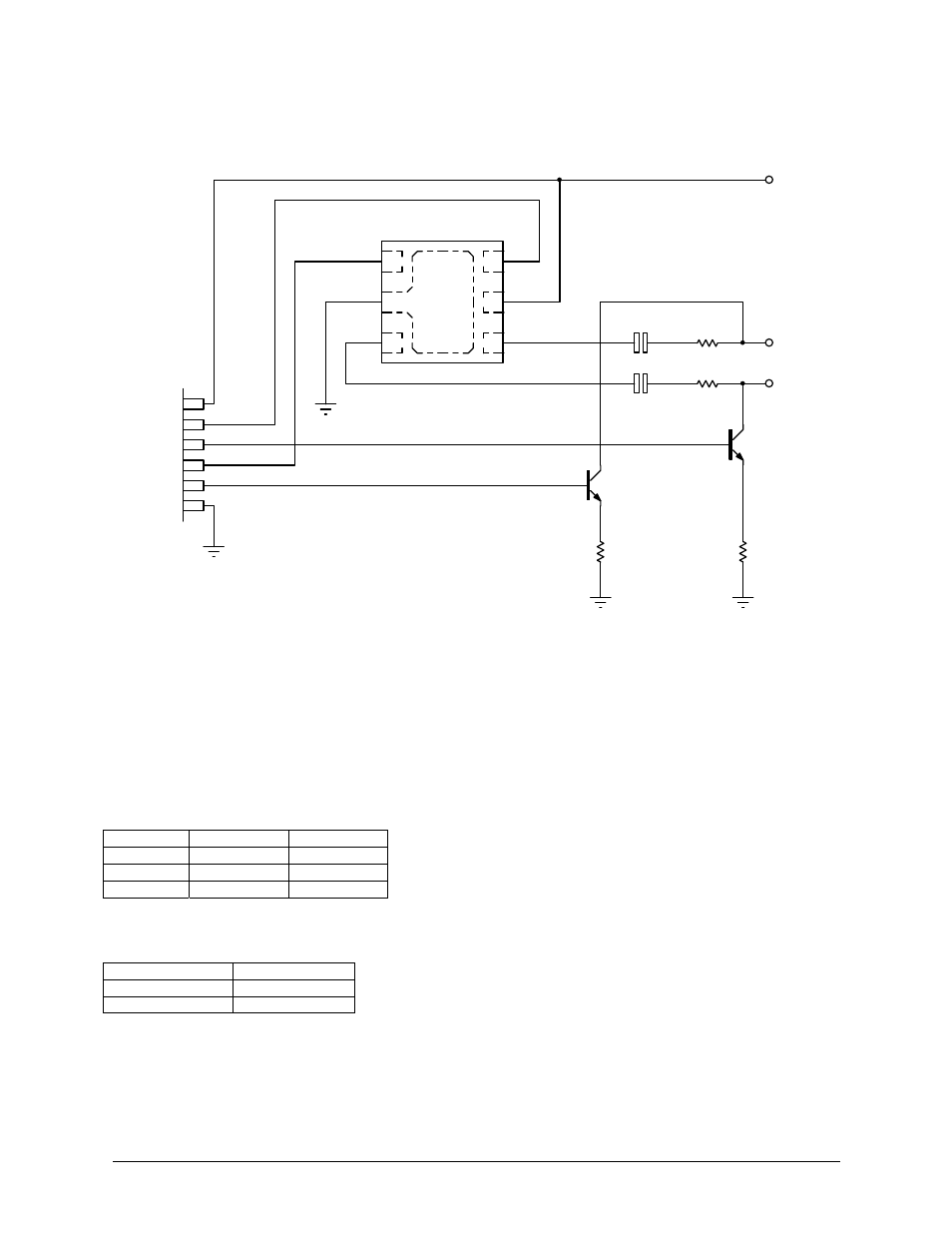
ZLNB254 Application Circuit
@ Zetex plc 2009
Vcc
R1
62k
LNB Downf eed 1
C1
100pF
P2
Micro-Controller
P3
P1
P4
Q1
BC846A
R2
100
Gnd
Vcc
Q2
BC846A
R4
100
R3
62k
C2
100pf
LNB Downf eed 2
ZLNB254
3
2
1
4
6
FIN1
GND
TD2
FIN2
TD1
5
VCC
The above circuit shows the additional components that will be used in a typical ZLNB254 application operating at a
Vcc of 5V and detecting 22kHz tones/tone bursts. The transistors Q1 and Q2 are not required for the ZLNB254
operation, they demonstrate how a DiSEqC 2.X (2 way communication) could be achieved.
The two detectors of the ZLNB254 are well matched to each other but thresholds of the tone detectors are dependent
on Vcc. The table below shows the recommended external input resistor (R1/R3 in above diagram) values needed to
meet the guaranteed threshold levels for a range of supply voltages.
Recommended Input Resistor Value vs Vcc Table
Vcc
R1 and R3
C1 and C2
3.3V 82K
100pF
5V 62K 100pF
6V 51K 100pF
Functional Table
FIN TD
Out
0 kHz
High
22 kHz
Low