Zr431, Adjustable precision zener shunt regulator, Absolute maximum ratings – Diodes ZR431 User Manual
Page 2: Recommended operating conditions, Electrical characteristics
ZR431
ADJUSTABLE PRECISION ZENER SHUNT REGULATOR
ZR431
Document number: DS33255 Rev. 6 - 2
2 of 9
October 2011
© Diodes Incorporated
ADVAN
CE I
N
F
O
RM
ATI
O
N
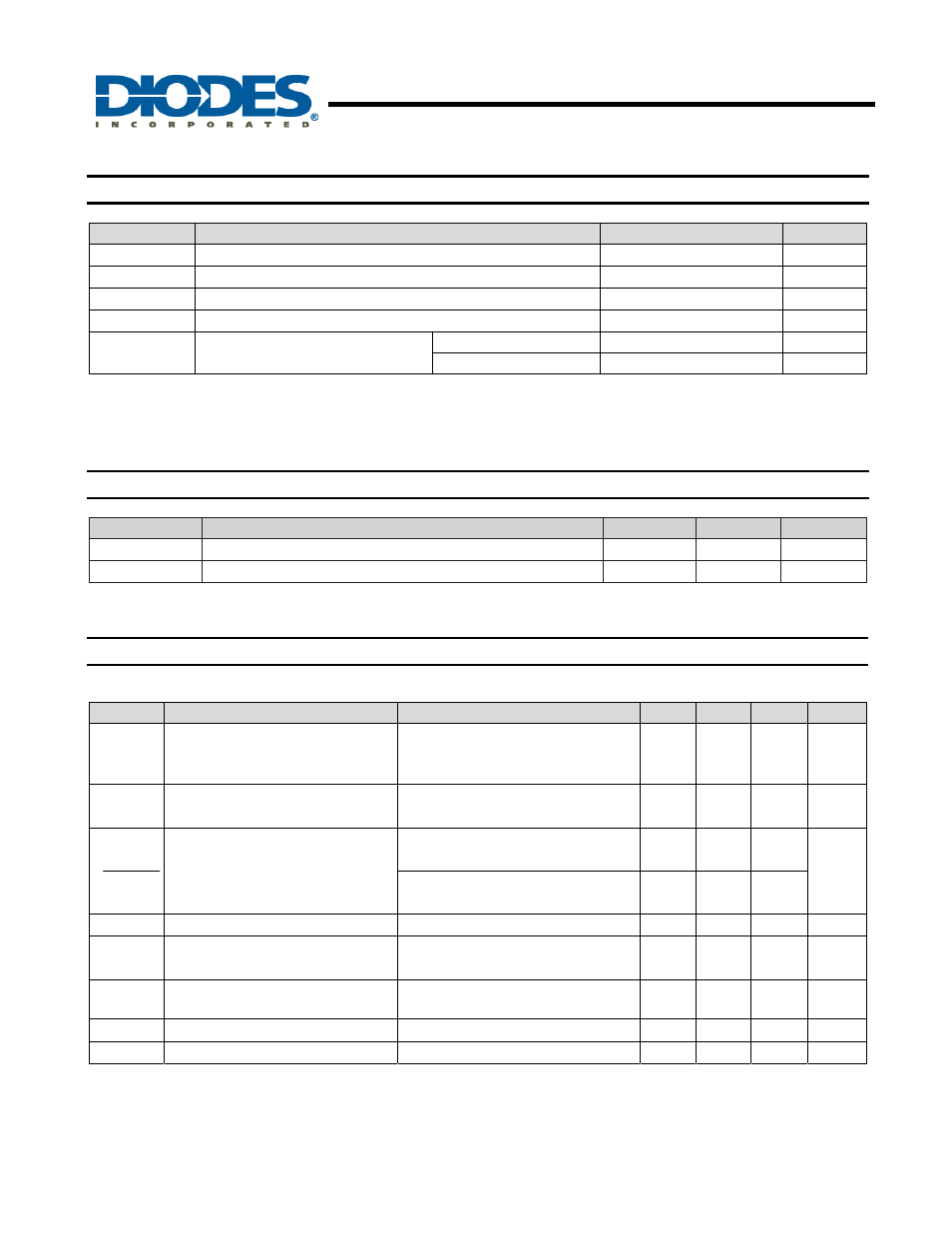
Absolute Maximum Ratings
(Note 2)
Symbol
Parameter
Rating
Unit
V
Z
Cathode Voltage
20
V
I
Z
Cathode Current
150
mA
T
A
Operating Temperature
-40 to +85
°
C
T
ST
Storage Temperature
-55 to +125
°
C
P
D
Power Dissipation (Notes 3, 4)
SOT23 330
mW
SOT223 2
W
Notes:
2. Operation above the absolute maximum rating may cause device failure. Operation at the absolute maximum ratings, for extended periods, may
reduce device reliability. Unless otherwise stated voltages specified are relative to the ANODE pin.
3.
T
J
, max =150°C.
4. Ratings apply to ambient temperature at 25°C.
Recommended Operating Conditions
(T
A
= 25
°C)
Symbol
Parameter
Min
Max
Unit
V
Z
Cathode Voltage
V
REF
20 V
I
Z
Cathode Current
0.05
100
mA
Electrical Characteristics
(T
A
= 25
°C unless otherwise specified)
Symbol
Parameter
Test Conditions
Min
Typ.
Max
Unit
V
REF
Reference voltage (Note 5) 2%
1 %
0.5%
I
L
= 10mA (Fig 1), V
Z
= V
REF
2.45
2.475
2.487
2.50
2.50
2.50
2.55
2.525
2.513
V
V
DEV
Deviation of reference input voltage
over temperature
I
L
= 10mA, V
Z
= V
REF
T
A
= Full range (Fig 1)
8.0
17 mV
ΔV
REF
ΔV
Z
Ratio of the change in reference
voltage to the change in cathode
voltage
V
Z
from V
REF
to 10V
I
Z
= 10mA (fig 2)
-1.85
-2.7
mV/V
V
Z
from 10V to 20V
I
Z
= 10mA (Fig 2)
-1.0
-2.0
I
REF
Reference input current
R1 = 10k, R2 = O/C, I
L
= 10mA (Fig 2)
0.12
1.0
μA
ΔI
REF
Deviation of reference input current
over temperature
R1 = 10k, R2 = O/C, I
L
= 10mA
T
A
= Full range (Fig 2)
0.04
0.2
μA
I
Z(MIN)
Minimum cathode current for
regulation
V
Z
= V
REF
(Fig 1)
35
50 µA
I
Z(OFF)
Off-state current
V
Z
= 20V, V
REF
= 0V (Fig 3)
0.1
μA
R
Z
Dynamic output impedance
V
Z
= V
REF
(Fig 1), f = 0Hz
0.75
Ω
Note 5:
0.5% and 1% SOT23 only
For definitions of reference voltage temperature coefficient and dynamic output impedance see NOTES following DC TEST CIRCUITS