Low power high-side current monitors, New prod uc t application information – Diodes ZXCT1107/1109/1110 User Manual
Page 13
ZXCT1107/1109/1110
LOW POWER HIGH-SIDE CURRENT MONITORS
ZXCT1107/1109/1110
Document number: DS35033 Rev. 3 - 2
13 of 16
JULY 2011
© Diodes Incorporated
A Product Line of
Diodes Incorporated
NEW PROD
UC
T
Application Information
(cont.)
Alternatively, the ZXCT1110 may be used with a reduced sense voltage if desired. From Equation 3, with
ε=4%,
8
.
1
082
.
0
V
SENSE
−
ε
=
= 0.082/(4-1.8) = 37.2mV
Equation 4 gives
R
SENSE
= 37.2mV/2A = 18.6m
Ω
A suitable preferred value is 20m
Ω. Then the sense voltage will be 2A * 20mΩ = 40mV.
Equation 5 gives
04
.
0
*
004
.
0
2
R
GAIN
=
= 12500
Ω
A suitable preferred value is 13k
Ω.
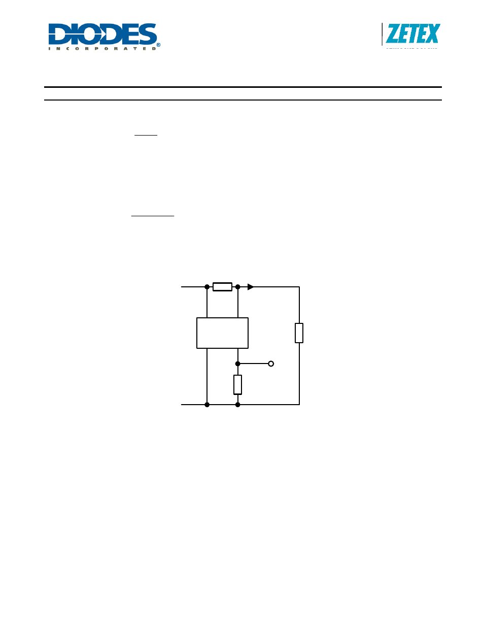
The alternative example circuit using the ZXCT1110 with a sense voltage of 40mV is shown in Figure 3, giving the required
overall accuracy of ±6%.
S+
ZXCT1110
S-
20m
Ω
V
SUPPLY
OUT
LOAD
GND
13k
GND
OUTPUT
V
OUT
I
LOAD
Figure 3. Example Circuit using ZXCT1110
Protection Against Load Short Circuit
In the event of a load short circuit or overload, a large proportion of the supply voltage may appear between the sense
terminals. The supply may be current limited, but there is normally a large reservoir capacitor which can deliver enough
energy to damage the ZXCT11xx before the supply voltage falls to a safe level due to current limit activation.
The ZXCT11xx is rated for a maximum sense voltage of +0.8V, but is safe if the input current is limited to ±8.5mA. In Figure
4, the resistor R
PROT
limits the current and therefore protects the current monitor device against load short circuit without
introducing significant current measurement error.