Low power high-side current monitors, New prod uc t application information – Diodes ZXCT1107/1109/1110 User Manual
Page 10
ZXCT1107/1109/1110
LOW POWER HIGH-SIDE CURRENT MONITORS
ZXCT1107/1109/1110
Document number: DS35033 Rev. 3 - 2
10 of 16
JULY 2011
© Diodes Incorporated
A Product Line of
Diodes Incorporated
NEW PROD
UC
T
Application Information
Description
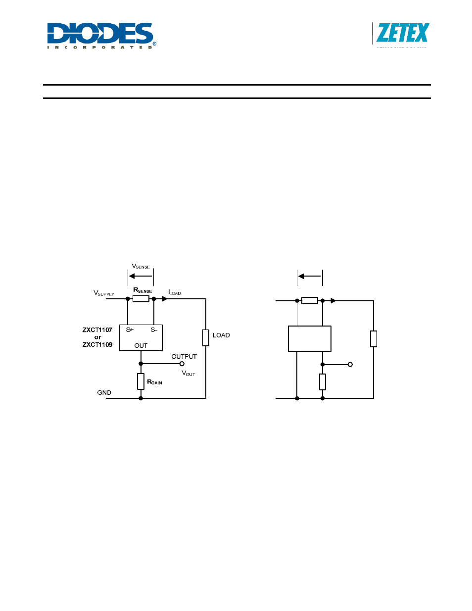
The current monitor ICs ZXCT1107, ZXCT1109 and ZXCT1110 all use a similar application circuit topology for high-side
current sensing, with small differences. The ZXCT1110 has a separate ground pin whereas the ZXCT1107 and ZXCT1109
do not. The use of ZXCT1110 allows reduction of the absolute current measurement error in some applications by providing
a reduced output offset current. The ZXCT1107 provides a mirror image pin assignment of the ZXCT1109 to ease PCB
layout in very small equipment designs.
The basic application circuit for each device is shown in Figure 1. Two external resistors are required. The resistor R
SENSE
is connected in the path of the current to be monitored. The resistor R
GAIN
converts the device output current to a voltage for
convenient processing by a further device, such as a comparator, amplifier or analog-to-digital converter within a
microcontroller system.
The current monitor output current is defined through the nominal transconductance of 4mA/V.
I
OUT
= 0.004 * V
SENSE
Amp
Equation
1
Then the resistors determine the output voltage as described below.
S+
ZXCT1110
S-
R
SENSE
V
SUPPLY
OUT
LOAD
GND
R
GAIN
GND
OUTPUT
V
OUT
I
LOAD
V
SENSE
Figure 1. Basic Application Circuit
Calculation of Resistor Values
In order to select R
SENSE
, a choice of sense voltage is required. This often involves a compromise between power efficiency
and accuracy for the given temperature range. The resistor must be small enough to avoid excessive volt drop between the
power supply and the load. However, the resistor must be large enough to avoid excessive current measurement error,
particularly random errors.
In a typical application, a digital system, perhaps a microcontroller, is set up to monitor the current. At a certain threshold
current level, I
LOADT
, the system is required to disconnect the load or report a fault. At this current level, the current
measurement error must be limited to a known value. The total percentage error comprises the inherent error in the
ZXCT1107/1109/1110 device and the tolerances of the two resistors R
SENSE
and R
GAIN
. The ZXCT1107/ZXCT1109
absolute error is shown in Table 1 with error limits drawn from the table of Electrical Characteristics above. This error varies
with V
SENSE
.