Zxct1010 – Diodes ZXCT1010 User Manual
Page 7
ISSUE 10 - JULY 2007
S E M I C O N D U C T O R S
ZXCT1010
7
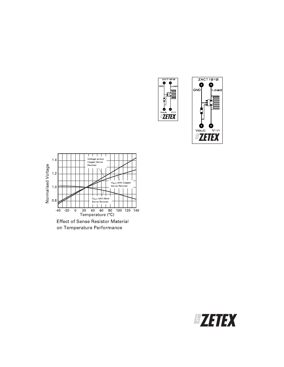
PCB trace shunt resistor for low cost
solution
The figure below shows output characteristics of the
device when using a PCB resistive trace for a low cost
solution in replacement for a conventional shunt
resistor. The graph shows the linear rise in voltage
across the resistor due to the PTC of the material and
demonstrates how this rise in resistance value over
temperature compensates for the NTC of the device.
The figure opposite shows a PCB layout suggestion.
The resistor section is 25mm x 0.25mm giving
approximately 150m
Ω using 1oz copper. The data
for the normalised graph was obtained using a 1A
load current and a 100
Ω output resistor. An
electronic version of the PCB layout is available at
www.zetex.com/isense
APPLICATIONS INFORMATION (Continued)
Layout shows area of shunt
resistor compared to SOT23-5
package. Not actual size
Actual Size
- PDS3200 (5 pages)
- PDS340 (5 pages)
- PDS340Q (5 pages)
- PDS360 (5 pages)
- PDS360Q (5 pages)
- PDS4150 (4 pages)
- PDS3100Q (5 pages)
- PDS3100 (5 pages)
- PDS1240CTL (5 pages)
- PDS1045 (5 pages)
- PDS1040L (5 pages)
- PDS1040CTL (5 pages)
- PDS1040 (5 pages)
- PD3S230L (5 pages)
- PD3S230H (3 pages)
- PDS5100Q (5 pages)
- PDS835L (5 pages)
- PDS760 (5 pages)
- PDS560 (5 pages)
- PDS540 (5 pages)
- PDS5100H (5 pages)
- PDS5100 (5 pages)
- PDS4200H (6 pages)
- SBL3060CTP (4 pages)
- SBL30L30CT (3 pages)
- SBL3045CTP (4 pages)
- SBL3040CTP (4 pages)
- SBL2060CTP (4 pages)
- SBL2030CT - SBL2060CT (3 pages)
- SBL2045CTP (4 pages)
- SBL1060CTP (4 pages)
- SBL1040CTP (4 pages)
- SBG3030CT - SBG3045CT (5 pages)
- SB520 - SB560 (3 pages)
- SB370 - SB3100 (3 pages)
- SB320 - SB360 (3 pages)
- SBR10U100CT (5 pages)
- SBR10U150CT (5 pages)
- SBR10A45SP5 (5 pages)
- SBR1060CT (5 pages)
- SBR1045SP5 (5 pages)
- SBR1045SD1 (4 pages)
- SBR1045D1 (5 pages)
- SBR1045CTL (4 pages)
- SBR1040CT (5 pages)