Zxct1010 – Diodes ZXCT1010 User Manual
Page 5
ISSUE 10 - JULY 2007
S E M I C O N D U C T O R S
ZXCT1010
5
The following lines describe how to scale a load
current to an output voltage.
V
sense
= V
in
- V
load
V
out
= 0.01 x V
sense
x R
out
1
E.g.
A 1A current is to be represented by a 100mV output
voltage:
1)Choose the value of R
sense
to give 50mV > V
sense
>
500mV at full load.
For example V
sense
= 100mV at 1.0A. R
sense
= 0.1/1.0
=> 0.1 ohms.
2)Choose R
out
to give V
out
= 100mV, when V
sense
=
100mV.
Rearranging
1
for R
out
gives:
R
out
= V
out
/(V
sense
x 0.01)
R
out
= 0.1 / (0.1 x 0.01) = 100
Ω
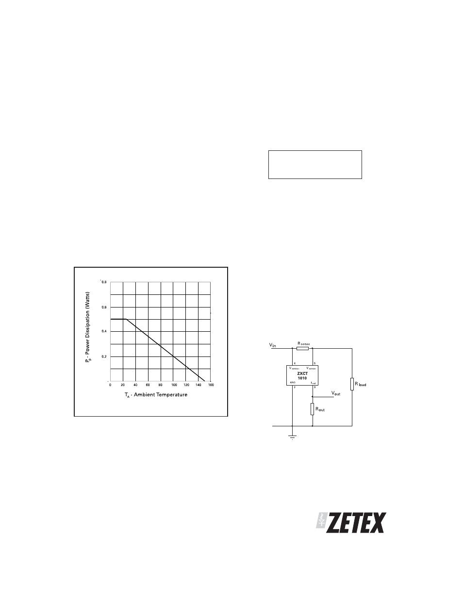
TYPICAL CIRCUIT APPLICATION
POWER DISSIPATION
The maximum allowable power dissipation of the
device for normal operation (Pmax), is a function of
the package junction to ambient thermal resistance
(
θja), maximum junction temperature (Tjmax), and
ambient temperature (Tamb), according to the
expression:
P
max
= (Tj
max
– T
amb
) /
θ
ja
The device power dissipation, P
D
is given by the
expression:
P
D
=I
out
.(V
in
-V
out
) Watts
Where R
load
represents any load including DC motors,
a charging battery or further circuitry that requires
monitoring, R
sense
can be selected on specific
requirements of accuracy, size and power rating.
APPLICATIONS INFORMATION