Zxct1009, High-side current monitor, Pin descriptions – Diodes ZXCT1009 User Manual
Page 2: Absolute maximum ratings, Electrical characteristics
ZXCT1009
HIGH-SIDE CURRENT MONITOR
ZXCT1009
Document number: DS33441 Rev. 12 - 2
2 of 8
April 2011
© Diodes Incorporated
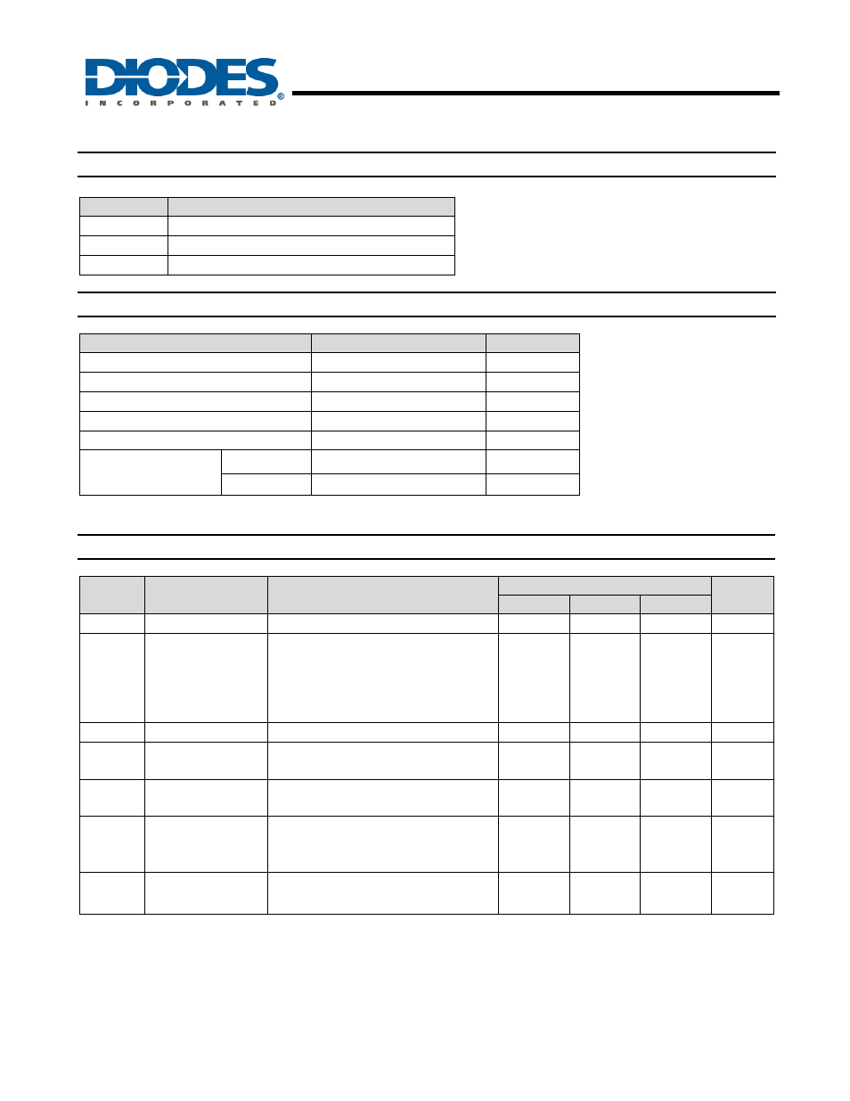
Pin Descriptions
Pin Name
Pin Function
V
SENSE+
Connection to supply voltage
V
SENSE-
Connection to load
I
OUT
Output current, proportional to measured current
Absolute Maximum Ratings
(T
A
= 25
°C)
Description
Rating
Unit
Voltage on any pin
(relative to IOUT)
-0.6 to 20
V
Continous output current, I
OUT
25 mA
Continuous sense voltage, V
SENSE
†
-0.5 to +5
V
Operating temperature, T
A
-40 to 85
°C
Storage temperature
-55 to 125
°C
Package power
dissipation @ T
A
= 25°C
(Derate to zero @ 125°C)
SOT23
450
mW
SM8 2
W
Operation above the absolute maximum rating may cause device failure. Operation at the absolute
maximum ratings for extended periods may reduce device reliability.
Electrical Characteristics
(T
A
= 25
°C, V
IN
= 5V, R
OUT
= 100
Ω)
Symbol
Parameter
Conditions
Limits
Units
Min
Typ
Max
V
IN
V
CC
range
2.5
20
V
I
OUT
1
Output Current
V
SENSE
= 0V
V
SENSE
= 10mV
V
SENSE
= 100mV
V
SENSE
= 200mV
V
SENSE
= 1V
1
90
0.975
1.95
9.6
4
104
1.002
2.0
9.98
15
120
1.025
2.05
10.2
µA
µA
mA
mA
mA
V
SENSE
†
Sense Voltage
0
2500
mV
I
SENSE-
V
SENSE -
Input Current
100
nA
A
CC
Accuracy
R
SENSE
= 0.1
Ω
V
SENSE
= 200mV
-2.5
2.5
%
G
M
Transconductance,
I
OUT
/V
SENSE
10000
µA/V
BW Bandwidth
V
SENSE(DC)
= 10mv, RF P
IN
= -40dBm
‡
V
SENSE(DC)
= 100mv, RF P
IN
= -20dBm
‡
300
2
kHz
MHz
Notes:
1. Includes input offset voltage contribution
†.
VSENSE is defined as the differential voltage between VSENSE+ and VSENSE-
.
VSENSE = VSENSE+ - VSENSE-
= VIN - VLOAD
= ILOAD x RSENSE
‡
-20dBm=63mVPP into 50Ω