Zxct1008, Application information (cont.), Ordering information – Diodes ZXCT1008 User Manual
Page 6
ZXCT1008
Document number: DS33441 Rev. 6 - 2
6 of 8
January 2014
© Diodes Incorporated
ZXCT1008
A Product Line of
Diodes Incorporated
Application Information (cont.)
PCB trace shunt resistor for low cost solution
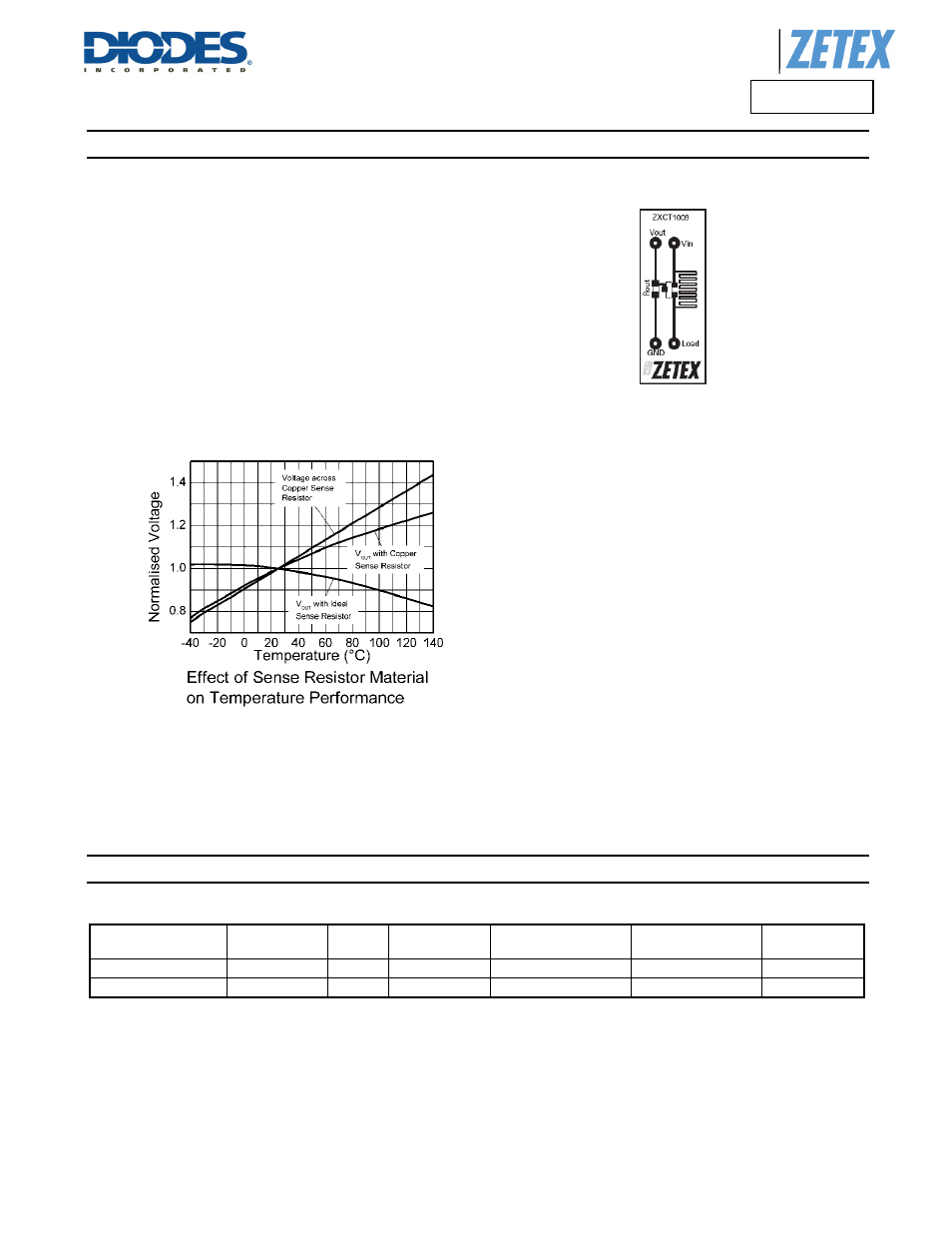
The figure below shows output characteristics of the device when using
a PCB resistive trace for a low cost solution in replacement for a
conventional shunt resistor. The graph shows the linear rise in voltage
across the resistor due to the PTC of the material and demonstrates
how this rise in resistance value over temperature compensates for the
NTC of the device.
The figure opposite shows a PCB layout suggestion. The resistor
section is 25mm x 0.25mm giving approximately 150mΩ using 1oz
copper. The data for the normalized graph was obtained using a 1A
load current and a 100Ω output resistor. An electronic version of the
PCB layout is available through Diodes applications group.
Effect of Sense Resisitor Material
on Temperature Performance
Layout shows area of shunt resistor compared to SOT23
package. Not actual size
.
Ordering Information
Device
AEC-Q100
level
Reel
Size
Tape Width
Quantity per Reel
Part Marking
Package
ZXCT1008FTA
Grade 3
7”
8mm
3000 Units
108
SOT23
ZXCT1008F-7
None
7”
8mm
3000 Units
108
SOT23
Note:
5. Pad layout as shown on Diodes Inc. suggested pad layout document AP02001, which can be found on our website at