Zxct1008, Application information – Diodes ZXCT1008 User Manual
Page 5
ZXCT1008
Document number: DS33441 Rev. 6 - 2
5 of 8
January 2014
© Diodes Incorporated
ZXCT1008
A Product Line of
Diodes Incorporated
Application Information
(cont.)
Where R
LOAD
represents any load including DC motors, a charging
battery or further circuitry that requires monitoring, R
SENSE
can be
selected on specific requirements of accuracy, size and power
rating.
An additional resistor, R
LIM
can be added in series with R
OUT
(as
below), to limit the current from I
OUT
. Any circuit connected to V
OUT
will be protected from input voltage transients. This can be of
particular use in automotive applications where load dump and other
common transients need to be considered. The Zener Z1 provides
additional protection for local dump, reverse battery and high
voltage transient incidents.
Assuming the worst case condition of V
OUT
= 0V; providing a low
impedance to a transient, the minimum value of R
LIM
is given by:
R
LIM(min
)
= (V
PK
– V
MAX)/IPK
V
PK
= Peak transient voltage to be withstood
V
MAX
= Maximum working voltage = 20V
I
PK
= Peak output current = 40mA
The maximum value of R
LIM
is set by V
IN(MIN)
, V
OUT(MAX)
and the
dropout voltage (see transfer characteristic on page 3) of the
ZXCT1008:
R
LIM(MAX)
= R
OUT
[V
IN(MIN)
– (V
DP
+ V
OUT(MAX)
)]/V
OUT(MAX)
V
I
N(MIN)
= Minimum Supply Operating Voltage
V
DP
= Dropout Voltage
V
OUT(MAX)
= Maximum Operating Output Voltage
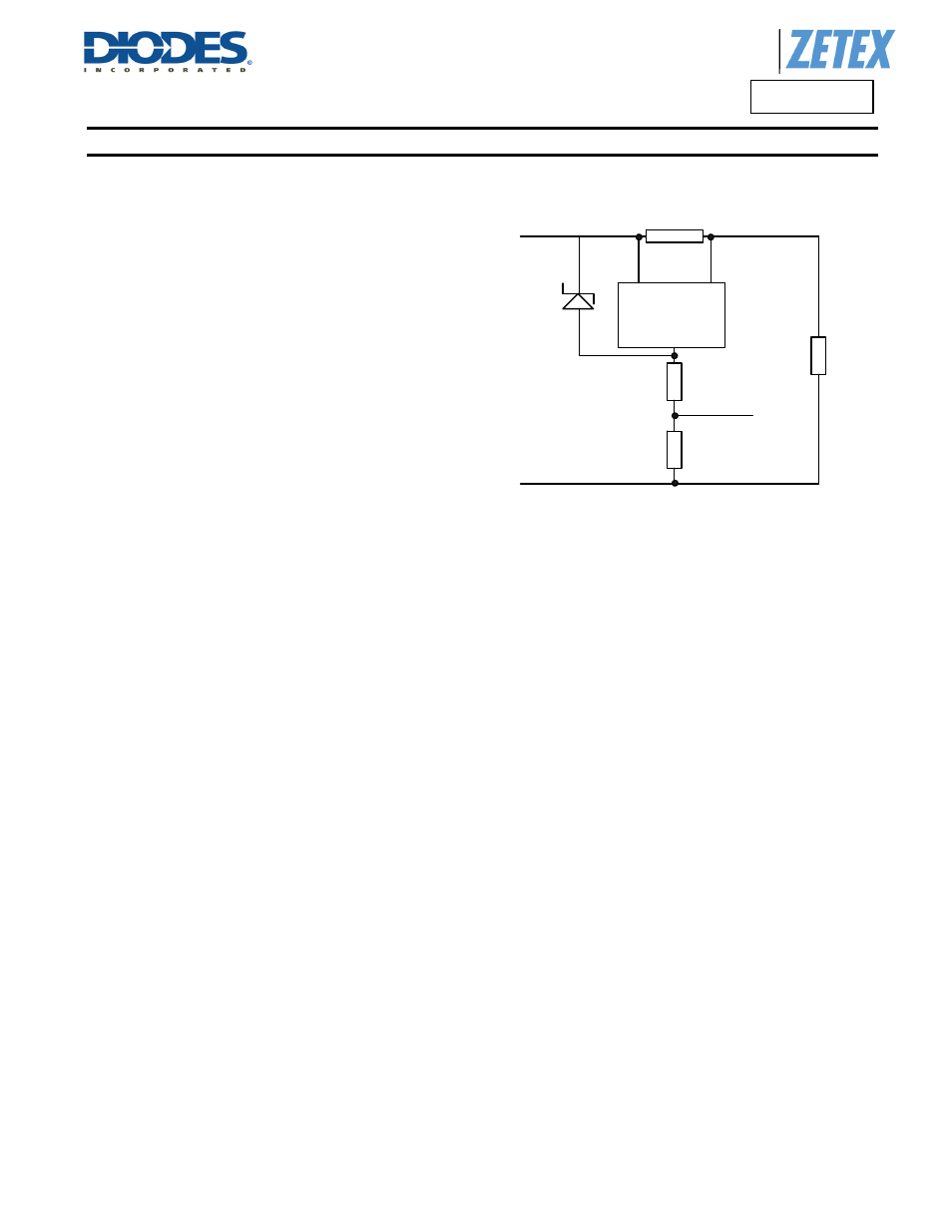
Typical Automotive Circuit Application
ZXCT1008
V
SENSE+
V
SENSE-
I
OUT
R
SENSE
R
lim
R
V
in
To load
V
out
R
load
Z1
Figure 1.0
ZXCT1008 with additional current limiting Resistor R
LIM
and Zener
Z1.