Zxct1080, High voltage high-side current monitor, Application information – Diodes ZXCT1080 User Manual
Page 9
ZXCT1080
HIGH VOLTAGE HIGH-SIDE CURRENT MONITOR
ZXCT1080
Document number: DS33454 Rev. 4 - 2
9 of 11
December 2011
© Diodes Incorporated
Application Information
(cont.)
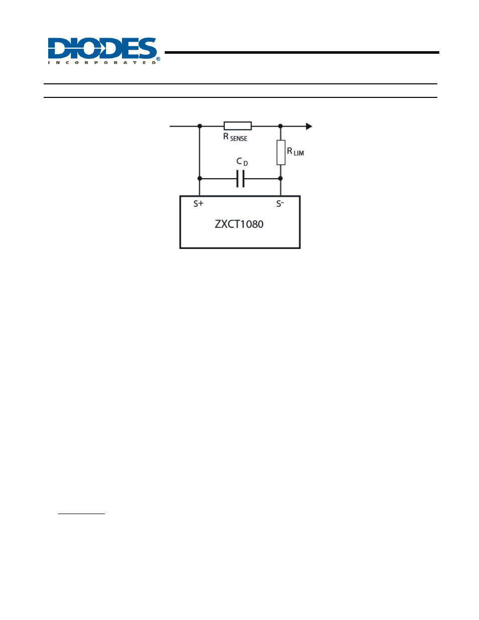
Fig. 21 Protection/Error Sources for ZXCT1080
Capacitor C
D
provides high frequency transient decoupling when used with R
LIM
; typical values are of the order 10pF.
For best performance R
SENSE
should be connected as close to the S+ (and SENSE) pins; minimizing any series resistance
with R
SENSE
.
When choosing appropriate values for R
SENSE
a compromise must be reached between in-line signal loss (including potential
power dissipation effects) and small signal accuracy.
Higher values for R
SENSE
gives better accuracy at low load currents by reducing the inaccuracies due to internal offsets. For
best operation the ZXCT1080 has been designed to operate with V
SENSE
of the order of 50mV to 150mV.
Current monitors' basic configuration is that of a unipolar voltage to current to voltage converter powered from a single supply
rail. The internal amplifier at the heart of the current monitor may well have a bipolar offset voltage but the output cannot go
negative; this results in current monitors saturating at very low sense voltages.
As a result of this phenomenon the ZXCT1080 has been specified to operate in a linear manner over a V
SENSE
range of
10mV to 150mV range, however it will still be monotonic down to V
SENSE
of 0V.
It is for this very reason that Diodes has specified an input offset voltage (V
O(10)
) at 10mV. The output voltage for any V
SENSE
voltage from 10mV to 150mV can be calculated as follows:
(
)
( )
V
G
V
V
10
SENSE
OUT
+
×
=
Alternatively the load current can be expressed as:
( )
(
)
GxR
V
V
I
SENSE
10
O
OUT
L
−
=