Zxct1080, High voltage high-side current monitor, Pin descriptions – Diodes ZXCT1080 User Manual
Page 2: Absolute maximum ratings, Recommended operating conditions
ZXCT1080
HIGH VOLTAGE HIGH-SIDE CURRENT MONITOR
ZXCT1080
Document number: DS33454 Rev. 4 - 2
2 of 11
December 2011
© Diodes Incorporated
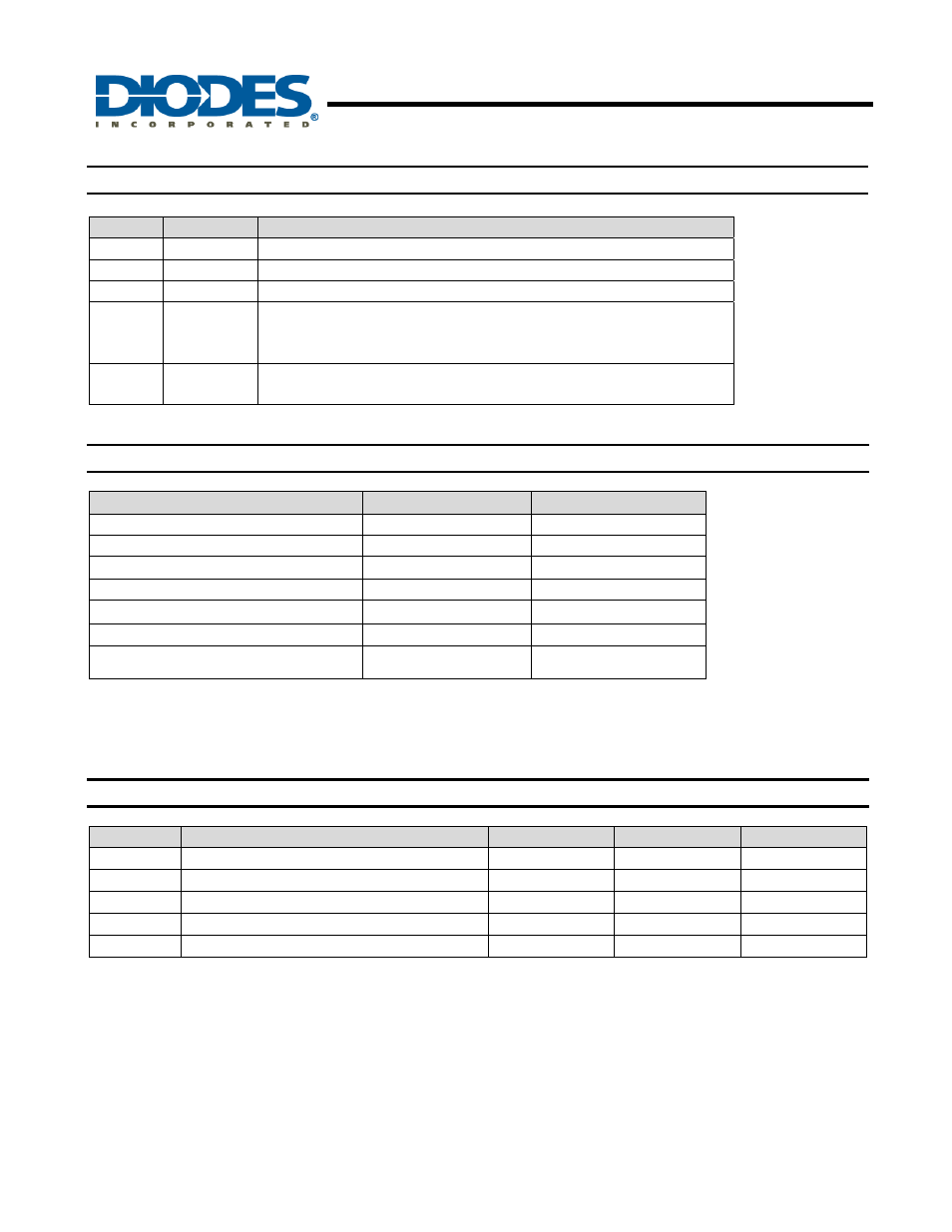
Pin Descriptions
Pin
Name
Description
1
V
CC
This is the analogue supply and provides power to internal circuitry
2 GND
Ground
pin
3
OUT
Output voltage pin. NMOS source follower with 20
μA bias to ground
4 S+
This is the positive input of the current monitor and has an input range from
60V down to 3V. The current through this pin varies with differential sense
voltage
5 S-
This is the negative input of the current monitor and has an input range
from 60V down to 3V
Absolute Maximum Ratings
(T
A
= 25
°C)
Parameter
Rating
Unit
Continuous voltage on S- and S+
-0.6 and 65
V
Voltage on all other pins
-0.6 and +14
V
Differential sense voltage, V
SENSE
(Note 1)
800 mV
Operating temperature
-40 to +125
°C
Storage Temperature
-55 to +150
°C
Maximum Junction Temperature
125
°C
Package Power Dissipation (Note 2)
300
(@ T
A
= 25°C)
mW
Operation above the absolute maximum rating may cause device failure. Operation at the absolute maximum ratings,
for extended periods, may reduce device reliabilty.
Note: 1.
V
SENSE
is defined as the differentail voltage between S+ and S- pins
2.
Assumes
θ
JA
= 420°C/W
Recommended Operating Conditions
Symbol
Parameter
Min
Max
Units
V
IN
Common-mode Sense+ Input Range
3
60
V
V
CC
Supply Voltage Range
4.5
12
V
V
SENSE
Differential Sense Input Voltage Range
0
0.15
V
V
OUT
Ouput Voltage Range
(Note 3)
0
1.5
V
T
A
Ambient Temperature Range
-40
125
°C
Note:
3. Based on 10x V
SENSE