Zxct1041, Absolute maximum ratings – Diodes ZXCT1041 User Manual
Page 2
ZXCT1041
Issue 2 - January 2008
2
www.zetex.com
© Zetex Semiconductors plc 2008
Absolute maximum ratings
Voltage on V
S-
and V
S+
-0.6 to 20V
Voltage on all other pins
-0.6V to (V
S+
or V
S-
) +0.6V
V
sense
[(V
S+
) - (V
S-
)]
+/-6V
Operating temperature, T
A
-40 to 125°C
Storage temperature
-55 to 150°C
Maximum junction temperature, T
J
150°C
Package power dissipation
300mW at T
A
= 25°C (De-rate to zero at 150°C)
Operation above the absolute maximum rating may cause device failure. Operation at the absolute maximum ratings, for
extended periods, may reduce device reliability.
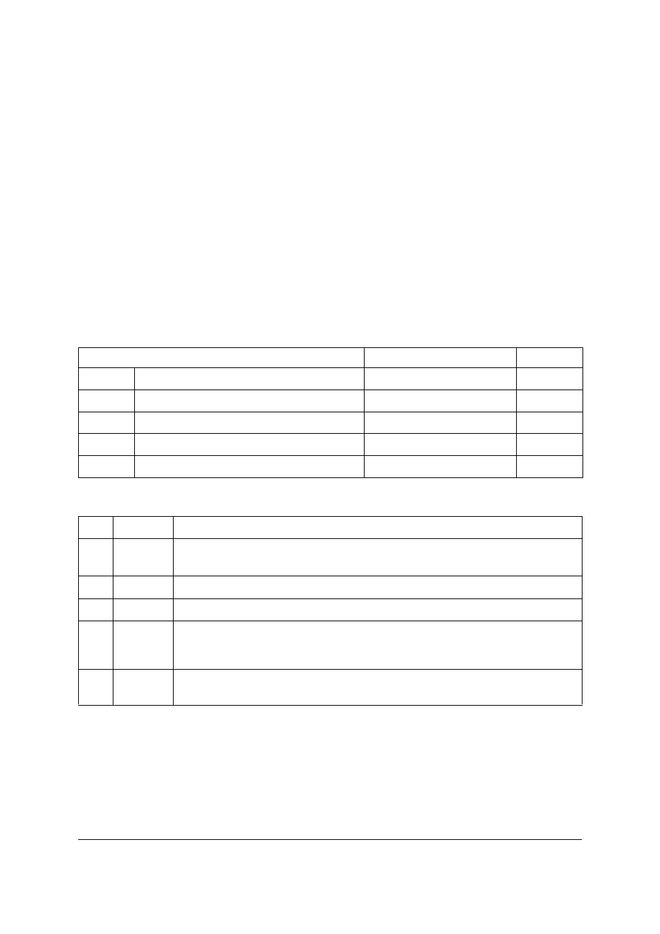
Recommended operating conditions
Pin function table
Parameter
Min.
Max.
Units
V
S±
Common-mode sense input range
2.7
20
V
Flag
Current direction flag output
0
V
S±
V
V
SENSE
Differential sense input voltage range
0
±0.8
V
V
OUT
Output voltage range
0
V
S±
-1.5
V
T
A
Ambient temperature range
-40
125
°C
Pin
Name
Description
1
Flag
This is the current direction pin. It is open collector and allows the logic high
level to be set independent of V
S+
voltage. Low indicates V
S+
is greater than V
S-
2
GND
Ground pin
3
OUT
Output voltage pin
4
S+
This is the positive input of the current monitor. It also acts as the supply
voltage pin providing current for internal circuitry. The current through this
pin varies with differential sense voltage
5
S-
This is the negative input of the current monitor. The current through this
pin varies with differential sense voltage