Zxbm1015 – Diodes ZXBM1015 User Manual
Page 4
ZXBM1015
ISSUE 3 - MAY 2007
4
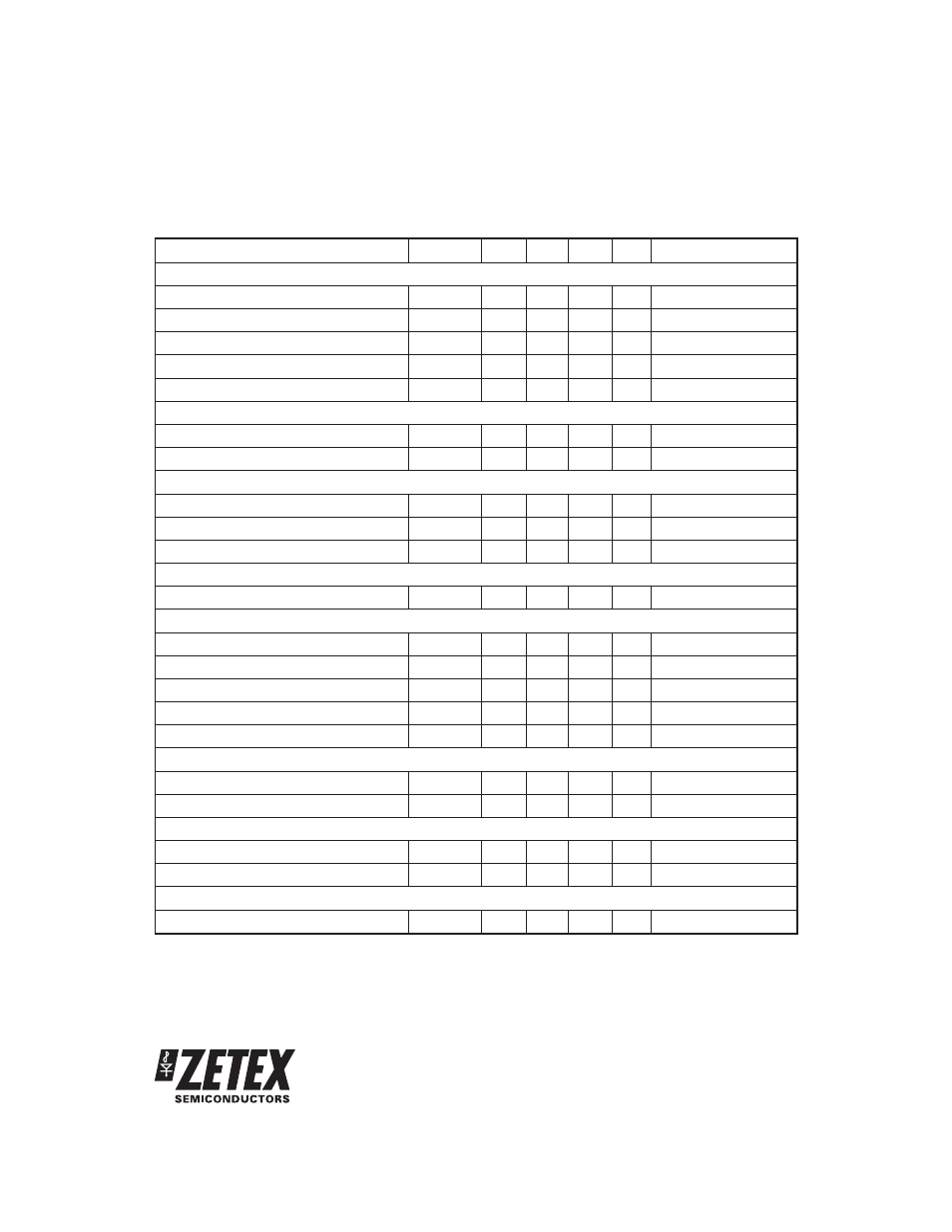
PARAMETER
SYMBOL
MIN.
TYP.
MAX.
UNIT CONDITIONS
PWM Oscillator
C
PWM
Charge Current
I
PWMC
-5.3
-
-9.1
A
C
PWM
Discharge Current
I
PWMD
55
-
105
A
C
PWM
High Threshold Voltage
V
THH
-
3
-
V
C
PWM
Low Threshold Voltage
V
THL
-
1
-
V
PWM Frequency
F
PWM
24
kHz
CPWM = 0.1nF
Reference Voltage
ThRef Voltage
V
ThRef
2.9
3.0
3.15
V
IOThRef = -10mA
ThRef Output Current
I
OThRef
-
-
-10
mA
Speed Control
SPD Voltage Minimum
V
SPDL
-
1
-
V
100% PWM Drive
SPD Voltage Maximum
V
SPDH
-
3
-
V
0% PWM Drive
SPD Input Current
I
ISPD
-
-0.4
-2
A Vin = 2V
Minumum Speed Setting
S
MIN
Input Current
I
SMIN
-
-0.25
-0.5
A Vin = 2V
Rotor Lock and Auto Restart
C
LCK
Charge Current
I
LCKC
-2.7
-
-5.2
A
C
LCK
Discharge Current
I
LCKD
0.2
-
0.42
A
C
LCK
High Threshold Voltage
V
THH
-
3
-
V
C
LCK
Low Threshold Voltage
V
THL
-
1
-
V
Lock condition On:Off ratio
-
1:12
-
Current Limit
Sense Input Current
I
Sense
-
-20
-100
nA
Vin = 1V, SetTh = 2V
SetTh Input Current
I
SetTh
-
-20
-100
nA
Vin = 2V, Sense = 1V
Output Flags
FG & RD Output Current
I
OL
-
-
16
mA
FG & RD Low Level Output Voltage
V
OL
-
-
0.5
V
IOL = 16mA
Commutation Delay
Commutation Delay
t
ComDel
48
-
112
s
ComDel Open Circuit
ELECTRICAL CHARACTERISTICS (at T
amb
= 25°C and Vcc = 12V) (Cont.)
Notes:
(1.) Measured with pins H+, H-, CLCK and CPWM = 0V and all other signal pins open circuit.
(2.) In this data sheet a negative sign for a current indicates current flowing out of the pin whilst no sign indicates current flowing into the pin