Zxld383 – Diodes ZXLD383 User Manual
Page 8
ZXLD383
ZXLD383
Document number: DS32189 Rev. 3 - 2
8 of 10
May 2010
© Diodes Incorporated
A Product Line of
Diodes Incorporated
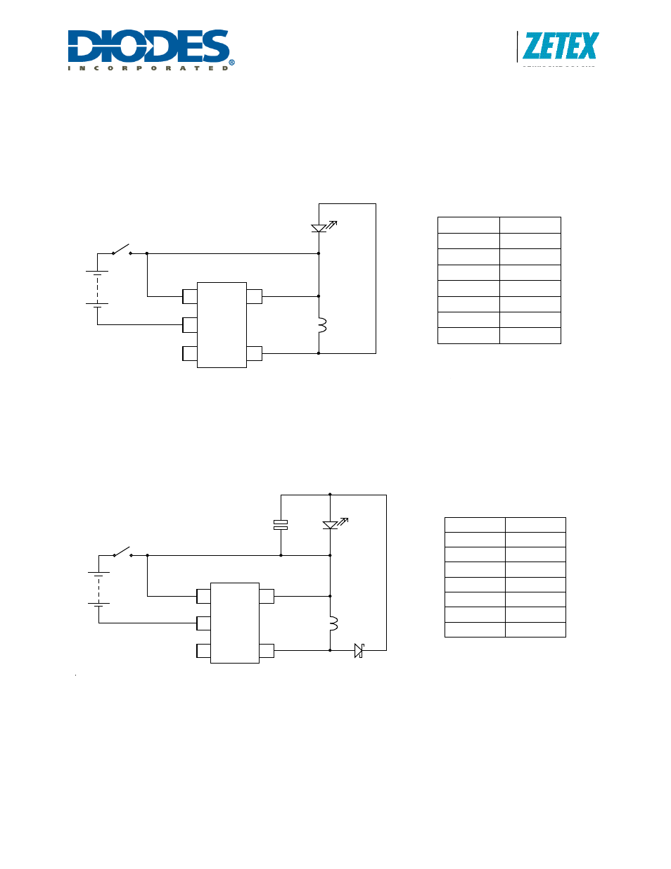
Buck-boost mode
Simple boost converters can run into problems when the input supply voltage is similar to or exceeds the intended load
voltage as there is usually a direct current path from the power source through to the load via the boost inductor. This path
does not require switching action and so is uncontrolled. When using the ZXLD383, this problem can be avoided by wiring
the cathode of the load LED to Vcc rather than ground. Without switching action, the LED is reverse-biased and so no
current can flow. When switching, the anode of the LED is driven to Vcc + Vf(led). The higher than normal output voltage
reduces the available output current as described earlier and this is shown in the typical data provided.
Notes: V
LED
= 3.5V
Low ripple buck-boost mode
The output of the Buck-Boost converter can be rectified and smoothed as with the standard circuit to give a low ripple
output to improve LED efficiency or to give a DC output for other loads.
Note: V
LED
=3.5V, D1=ZHCS1000, C1 = 1uF (low ESR)
L
I
L E D
(u H )
(m A )
4 7
5
2 2
9 .7
1 0
2 1 .7
6 .8
3 4
4 .7
4 3
D 1
LE D
C 1
Z XLD 383
3
2
1
4
E N A
G N D
V O U T
5
V C C
L1
N C
3V
L
I
L E D
(u H )
(m A )
4 7
5 .5
2 2
1 0 .3
1 0
2 3 .2
6 .8
3 6 .7
4 .7
4 6 .2
Z XLD 383
3
2
1
4
E N A
G N D
V O U T
5
V C C
L1
LE D
N C
3V