Zldo1117, Typical application circuits – Diodes ZLDO1117 User Manual
Page 8
ZLDO1117
Document number: DS32018 Rev. 6 - 2
8 of 14
July 2012
© Diodes Incorporated
ZLDO1117
A Product Line of
Diodes Incorporated
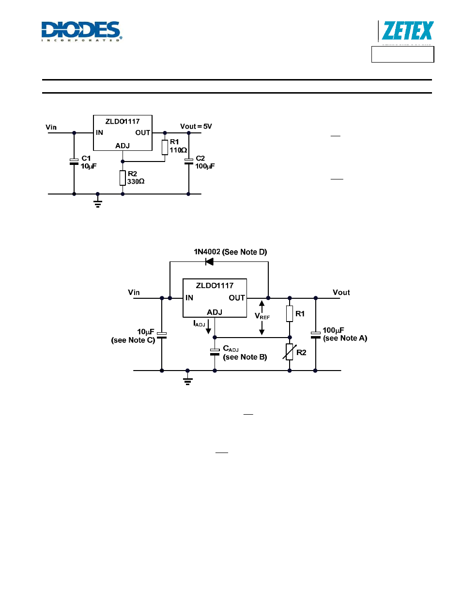
Typical Application Circuits
Figure 1 Basic Adjustable Regulator with 5V Output
Using
⎩
⎨
⎧
⎭
⎬
⎫
+
•
=
1
R
2
R
1
25
.
1
V
OUT
then the output voltage becomes:
V
0
.
5
110
330
1
25
.
1
V
OUT
=
⎩
⎨
⎧
⎭
⎬
⎫
+
•
=
Figure 2 Adjustable Regulator with IADJ Errors
2
R
I
1
R
2
R
1
25
.
1
V
ADJ
OUT
•
+
⎩
⎨
⎧
⎭
⎬
⎫
+
•
=
Because I
ADJ
typically is 55
μA, its effect is negligible in most applications.
V
02
.
5
330
10
55
110
330
1
25
.
1
V
6
OUT
=
⎩
⎨
⎧
⎭
⎬
⎫
•
•
+
+
•
=
−
~ 0.4%
A.
Output capacitor selection is critical for regulator stability. Larger C
out
values benefit the regulator by improving transient response and loop
stability.
B. C
ADJ
can be used to improve ripple rejection. If C
ADJ
is used, a C
out
that is larger in value than C
ADJ
must be used.
C. C
in
is recommended if ZLDO1117 is not located near the power supply filter.
D.
An external diode is recommended to protect the regulator if the input instantaneously is shorted to GND.
E.
This device is designed to be stable with tantalum and MLCC capacitors with an ESR less than 0.47
Ω.