Pin descriptions, Absolute maximum ratings, Zldo1117 – Diodes ZLDO1117 User Manual
Page 2: A product line of diodes incorporated
ZLDO1117
Document number: DS32018 Rev. 6 - 2
2 of 14
July 2012
© Diodes Incorporated
ZLDO1117
A Product Line of
Diodes Incorporated
Pin Descriptions
Pin
Name
I/O
Pin
Number
Function
Adj (GND)
I
1
A resistor divider from this pin to the V
OUT
pin and ground sets the output voltage (Ground only for
Fixed-Mode).
V
OUT
O 2
The output of the regulator. A minimum of 4.7µF capacitor (0.05
Ω ≤ ESR ≤ 0.5Ω) must be connected
from this pin to ground to insure stability. For improved ac load response a larger output capacitor is
recommended.
V
IN
I 3
The input pin of regulator. Typically a large storage capacitor (0.05
Ω ≤ ESR ≤ 0.5Ω) is connected from
this pin to ground to ensure that the input voltage does not sag below the minimum dropout voltage
during the load transient response. This pin must always be 1.3V higher than V
OUT
in order for the
device to regulate properly.
Absolute Maximum Ratings
(@T
A
= +25°C, unless otherwise specified.)
Symbol Parameter
Rating
Unit
V
IN
Input Supply Voltage (Relative to Ground)
-0.03 to +18
V
T
J
Junction
Temperature
+150
°C
Power Dissipation
See SOA Curve
T
ST
Storage Temperature
-65 to +150
°C
Unless otherwise stated voltages specified are relative to the ANODE pin.
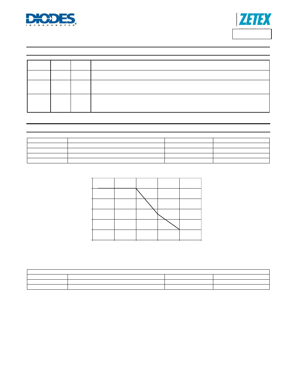
Safe Operation Area (SOA) Curve
ESD Susceptibility
Symbol Parameter
Rating
Unit
HBM
Human Body Model
4
kV
MM Machine
Model
400
V
Stresses greater than the 'Absolute Maximum Ratings' specified above, may cause permanent damage to the device. These are stress ratings only; functional
operation of the device at these or any other conditions exceeding those indicated in this specification is not implied. Device reliability may be affected by exposure to
absolute maximum rating conditions for extended periods of time.
Semiconductor devices are ESD sensitive and may be damaged by exposure to ESD events. Suitable ESD precautions should be taken when handling and
transporting these devices
0
0.2
0.4
0.6
0.8
1
1.2
0
5
10
15
20
25
V
IN
- V
OUT
(V)
I
LO
A
D
(A
)
SOA