Zldo330, Applications, Switched supply input vin vout gnd – Diodes ZLDO330 User Manual
Page 8: Output
ZLDO330
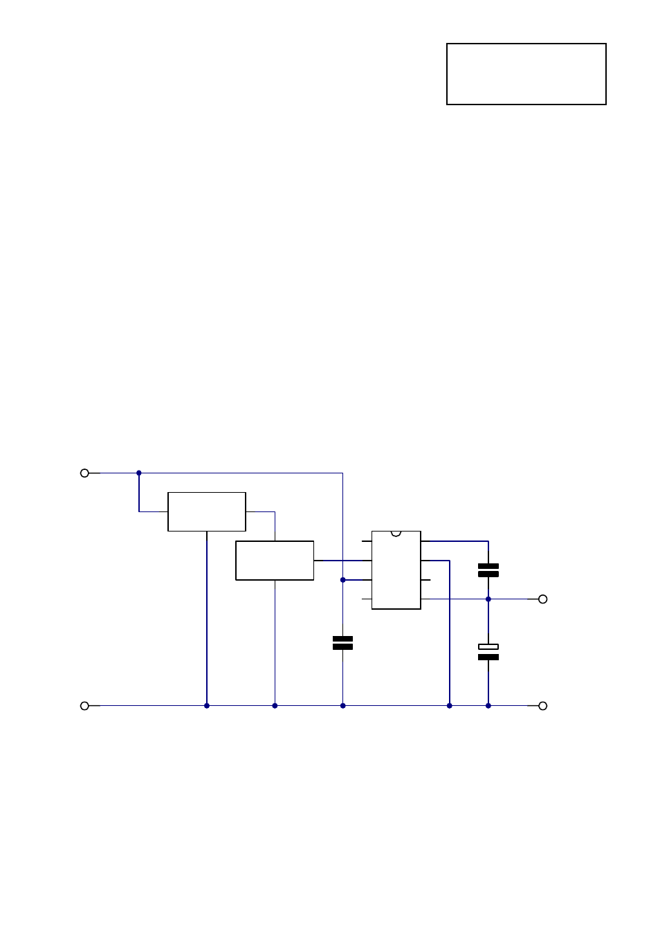
5). Logic Controlled Power Supply
Fig.4 shows all that is necessary to allow a
microprocessor to control a power supply
based on the ZLDO330. The Shutdown Control
pin (pin 2), is a logic compatible input that
disables the regulator when a voltage in
excess of 1.5V is applied. The current required
to drive this input is less than 10uA. When the
regulator is shutdown in this way, the
quiescent current of the ZLDO330 falls to
around 11
µ
A. This makes the regulator
suitable for a wide range of battery powered
applications where intermittent operation
occurs. The shutdown control pin should not
be taken to a voltage higher than Vin if low
quiescent supply current is important. The
shutdown control is a high impedance input
and so if not required, should be wired to the
ground pin (pin 7).
APPLICATIONS
Spg
D/C
Vout
LBF
SC
Vin
N/C
Gnd
IC2
ZLDO330
C2
1uF
C1
10pF
C3
100nF
0V
+ 3.3V
Microproc.
System
Switched
Supply Input
Vin Vout
Gnd
IC1
ZSR330
Output
0V
+ 5V
to 20V
Figure 4
4-69