Thermal resistance, Absolute maximum ratings – Diodes ZXM66P03N8 User Manual
Page 2
ZXM66P03N8
S E M I C O N D U C T O R S
ISSUE 1 - JANUARY 2006
2
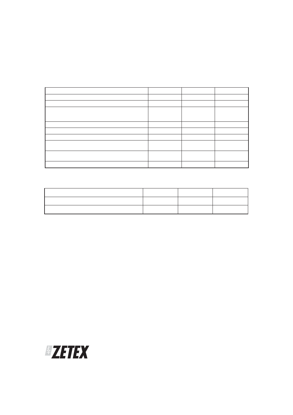
THERMAL RESISTANCE
PARAMETER
SYMBOL
VALUE
UNIT
Junction to Ambient (a)
RθJA
80
°C/W
Junction to Ambient (b)
RθJA
50
°C/W
NOTES
(a) For a device surface mounted on 25mm x 25mm FR4 PCB with high coverage of single sided 1oz copper, in still air conditions
(b) For a device surface mounted on FR4 PCB measured at t
р10 secs.
(c) Repetitive rating 25mm x 25mm FR4 PCB, D = 0.05, pulse width 10
s - pulse width limited by maximum junction temperature.
ABSOLUTE MAXIMUM RATINGS
PARAMETER
SYMBOL
LIMIT
UNIT
Drain-Source Voltage
VDSS
-30
V
Gate- Source Voltage
VGS
±20
V
Continuous Drain Current VGS=-10V; TA=25°C(b)
VGS=-10V; TA=70°C(b)
VGS=-10V; TA=25°C(a)
ID
-7.9
-6.3
-6.25
A
Pulsed Drain Current (c)
IDM
-28
A
Continuous Source Current (Body Diode)(b)
IS
-4.1
A
Pulsed Source Current (Body Diode)(c)
ISM
-28
A
Power Dissipation at TA=25°C (a)
Linear Derating Factor
PD
1.56
12.5
W
mW/°C
Power Dissipation at TA=25°C (b)
Linear Derating Factor
PD
2.5
20
W
mW/°C
Operating and Storage Temperature Range
Tj:Tstg
-55 to +150
°C