Zxtc6720mc, Pnp - electrical characteristics, A product line of diodes incorporated – Diodes ZXTC6720MC User Manual
Page 6
ZXTC6720MC
Document number: DS31929 Rev. 3 - 2
6 of 9
January 2011
© Diodes Incorporated
A Product Line of
Diodes Incorporated
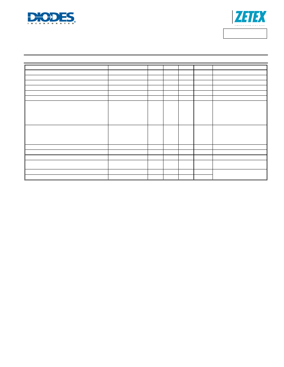
ZXTC6720MC
PNP - Electrical Characteristics
@T
A
= 25°C unless otherwise specified
Characteristic Symbol
Min
Typ
Max
Unit
Test
Condition
Collector-Base Breakdown Voltage
V
(BR)CBO
-70 -150 -
V I
C
= -100µA
Collector-Emitter Breakdown Voltage (Note 11)
V
(BR)CEO
-70 -125 -
V I
C
= -10mA
Emitter-Base Breakdown Voltage
V
(BR)EBO
-7 -8.5 -
V I
E
= -100µA
Collector Cutoff Current
I
CBO
- -
-100
nA
V
CB
= -55V
Emitter Cutoff Current
I
EBO
- -
-100
nA
V
EB
= -6V
Collector Emitter Cutoff Current
I
CES
- -
-100
nA
V
CE
= -55V
Static Forward Current Transfer Ratio
(Note 11)
h
FE
200
300
175
40
-
470
450
275
60
10
-
-
-
-
-
-
I
C
= -10mA, V
CE
= -5V
I
C
= -100mA, V
CE
= -5V
I
C
= -1A, V
CE
= -5V
I
C
= -1.5A, V
CE
= -5V
I
C
= -3A, V
CE
= -5V
Collector-Emitter Saturation Voltage
(Note 11)
V
CE(sat)
-
-
-
-
-35
-135
-140
-175
-50
-200
-220
-270
mV
I
C
= -0.1A, I
B
= -10mA
I
C
= -0.5A, I
B
= -20mA
I
C
= -1.0A, I
B
= -100mA
I
C
= -1.5A, I
B
= -200mA
Base-Emitter Turn-On Voltage (Note 11)
V
BE(on)
- 0.78
1.00 V
I
C
= -1.5A, V
CE
= -5V
Base-Emitter Saturation Voltage (Note 11)
V
BE(sat)
- 0.94
1.05 V
I
C
= -1.5A, I
B
= -200mA
Output Capacitance
C
obo
- 14 20 pF
V
CB
= -10V. f = 1MHz
Transition Frequency
f
T
150 180 -
MHz
V
CE
= -10V, I
C
= -50mA,
f = 100MHz
Turn-on Time
t
on
- 40 - ns
V
CC
= -50V, I
C
= -1A
I
B1
= I
B2
= -50mA
Turn-off Time
t
off
- 700 - ns
Notes:
11. Measured under pulsed conditions. Pulse width
≤ 300µs. Duty cycle ≤ 2%.