Electrical characteristics, Zxt1053ak, A product line of diodes incorporated – Diodes ZXT1053AK User Manual
Page 4
ZXT1053AK
Document number: DS33644 Rev. 5 - 2
4 of 7
November 2013
© Diodes Incorporated
A Product Line of
Diodes Incorporated
ZXT1053AK
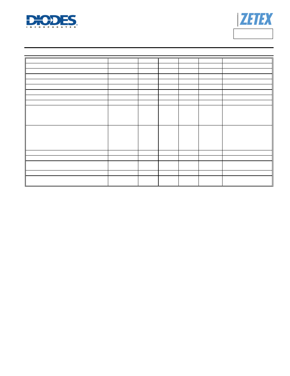
Electrical Characteristics
(@T
A
= +25°C, unless otherwise specified.)
Characteristic Symbol
Min
Typ.
Max
Unit
Test
Condition
Collector-Base Breakdown Voltage
BV
CBO
150 240 —
V
I
C
= 100µA
Collector-Base Breakdown Voltage
BV
CES
150 240 —
V
I
C
= 100µA
Collector-Emitter Breakdown Voltage (Note 11)
BV
CEO
75 90 —
V
I
C
= 10mA
Collector-Emitter Breakdown Voltage
BV
CEV
150 240 —
V
I
C
= 1µA, V
EB
= 1V
Emitter-Base Breakdown Voltage
BV
EBO
7 8.7 —
V
I
E
= 100µA
Collector Cutoff Current
I
CBO
—
<1 10 nA
V
CB
= 120V
Emitter Cutoff Current
I
EBO
— <1 10 nA
V
EB
= 6V
Emitter Cutoff Current
I
CES
— <1 10 nA
V
CE
= 120V
DC current transfer Static ratio (Note 9)
h
FE
260
300
50
10
375
450
75
25
—
1200
—
—
—
I
C
= 10mA, V
CE
= 2V
I
C
= 1A, V
CE
= 2V
I
C
= 5A, V
CE
= 2V
I
C
= 10A, V
CE
= 2V
Collector-Emitter Saturation Voltage (Note 11)
V
CE(sat)
—
—
—
—
—
19
70
120
140
350
30
95
160
190
460
mV
I
C
= 0.2A, I
B
= 20mA
I
C
= 1A, I
B
= 100mA
I
C
= 1A, I
B
= 10mA
I
C
= 2A, I
B
= 100mA
I
C
= 5A, I
B
= 200mA
Base-Emitter Saturation Voltage (Note 11)
V
BE(sat)
—
1.0 1.1 V
I
C
= 5A, I
B
= 200mA
Base-Emitter Turn-on Voltage (Note 11)
V
BE(on)
—
0.925 1.05
V I
C
= 5A, V
CE
= 2V
Transitional Frequency
f
T
—
140 — MHz
I
C
= 50mA, V
CE
= 10V
f = 100MHz
Output capacitance
C
OBO
—
21 30 pF
V
CB
= 10V, f = 1MHz,
Switching times
t
ON
t
OFF
—
162
900
— nS
I
C
=
2A, V
CC
= 50V,
I
B1
= I
B2
= 20mA
Notes:
11. Measured under pulsed conditions. Pulse width ≤ 300μs. Duty cycle ≤2%.