Characteristic, Symbol, Value – Diodes ZTX651 User Manual
Page 2: Unit, Jedec class, Ztx651, Maximum ratings, Thermal characteristics, Esd ratings
ZTX651
Document number: DS33283 Rev. 3 - 2
2 of 7
May 2013
© Diodes Incorporated
ZTX651
A Product Line of
Diodes Incorporated
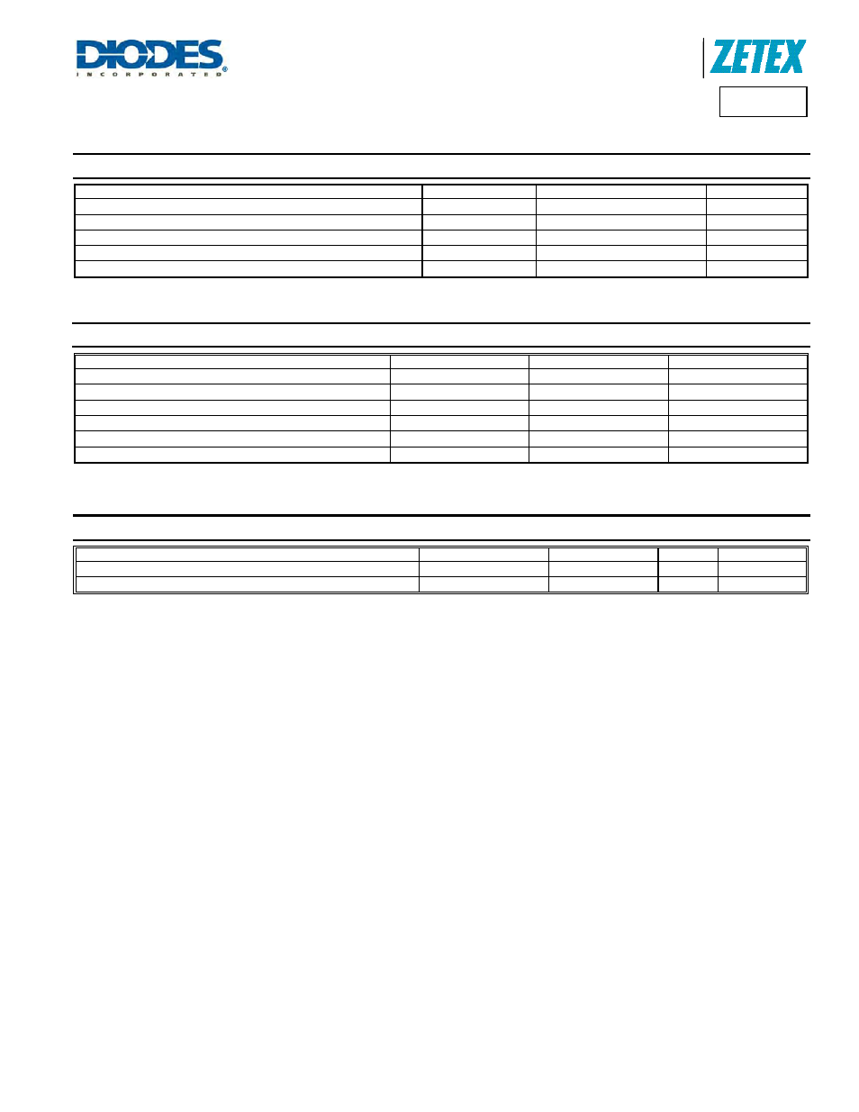
Maximum Ratings
(@T
A
= +25°C, unless otherwise specified.)
Characteristic
Symbol
Value
Unit
Collector-Base Voltage
V
CBO
80
V
Collector-Emitter Voltage
V
CEO
60
V
Emitter-Base Voltage
V
EBO
7
V
Continuous Collector Current
I
C
2
A
Peak Pulse Current
I
CM
6
A
Thermal Characteristics
(@T
A
= +25°C, unless otherwise specified.)
Characteristic
Symbol
Value
Unit
Power Dissipation (Note 6)
P
D
1.5
W
Power Dissipation (Note 7)
P
D
1
W
Thermal Resistance Junction to Ambient (Note 6)
R
ΘJA
116
°C/W
Thermal Resistance Junction to Ambient (Note 7)
R
ΘJA
175
°C/W
Thermal Resistance Junction to Lead (Note 8)
R
ΘJL
70
°C/W
Operating and Storage Temperature Range
T
J,
T
STG
-55 to +200
°C
ESD Ratings
(Note 9)
Characteristic
Symbol
Value
Unit
JEDEC Class
Electrostatic Discharge - Human Body Model
ESD HBM
4,000
V
3A
Electrostatic Discharge - Machine Model
ESD MM
400
V
C
Notes:
6. For a through-hole device mounted at the seating plane (2.5mm lead length) with the collector lead on 25mm x 25mm 1oz copper
that is on a single-sided FR4 PCB; device is measured under still air conditions whilst operating in a steady-state.
7. Same as note (5), except the device is mounted on minimum recommended pad layout with 12mm lead length from the bottom of package to the board.
8. Thermal resistance from junction to solder-point at the seating plane (2.5mm from the bottom of package along the collector lead).
9. Refer to JEDEC specification JESD22-A114 and JESD22-A115.