Sbr660ctlq, Maximum ratings (per leg), Thermal characteristics – Diodes SBR660CTLQ User Manual
Page 2: Per leg), Electrical characteristics
SBR is a registered trademark of Diodes Incorporated.
SBR660CTLQ
Document number: DS36093 Rev. 1 - 2
2 of 6
October 2012
© Diodes Incorporated
SBR660CTLQ
Maximum Ratings (Per Leg)
(@T
A
= +25°C, unless otherwise specified.)
Single phase, half wave, 60Hz, resistive or inductive load.
For capacitance load, derate current by 20%.
Characteristic Symbol
Value
Unit
Peak Repetitive Reverse Voltage
Working Peak Reverse Voltage
DC Blocking Voltage
V
RRM
V
RWM
V
RM
60 V
Average Rectified Output Current
(Per Leg)
(Total)
I
O
3
6
A
Non-Repetitive Peak Forward Surge Current 8.3ms
Single Half Sine-Wave Superimposed on Rated Load
I
FSM
80 A
Repettitive Peak Avalanche Power (1
μs, +25 ºC)
P
ARM
10000 W
Non-Repetitive Avalanche Energy
(T
J
= +25°C, I
AS
= 5A, L = 8.5mH)
E
AS
190 mJ
Thermal Characteristics
(Per Leg)
Characteristic Symbol
Value
Unit
Typical Thermal Resistance (per leg) (Note 5)
R
θJC
2 °C/W
Operating and Storage Temperature Range
T
J
, T
STG
-65 to +150
ºC
Electrical Characteristics
(Per Leg)
(@T
A
= +25°C, unless otherwise specified.)
Characteristic Symbol
Min
Typ
Max
Unit
Test
Condition
Leakage Current (Note 6)
I
R
-
-
-
5
0.3
12
mA
V
R
= 60V, T
J
= +25ºC
V
R
= 60V, T
J
= +125ºC
Forward Voltage Drop
V
F
- -
0.57
V
I
F
= 3A, T
J
= +25ºC
Notes:
5. Device mounted on Polymide substrate, 125mm
2
Copper pad, double-sided, PC Board.
6. Short duration pulse test used to minimize self-heating effect.
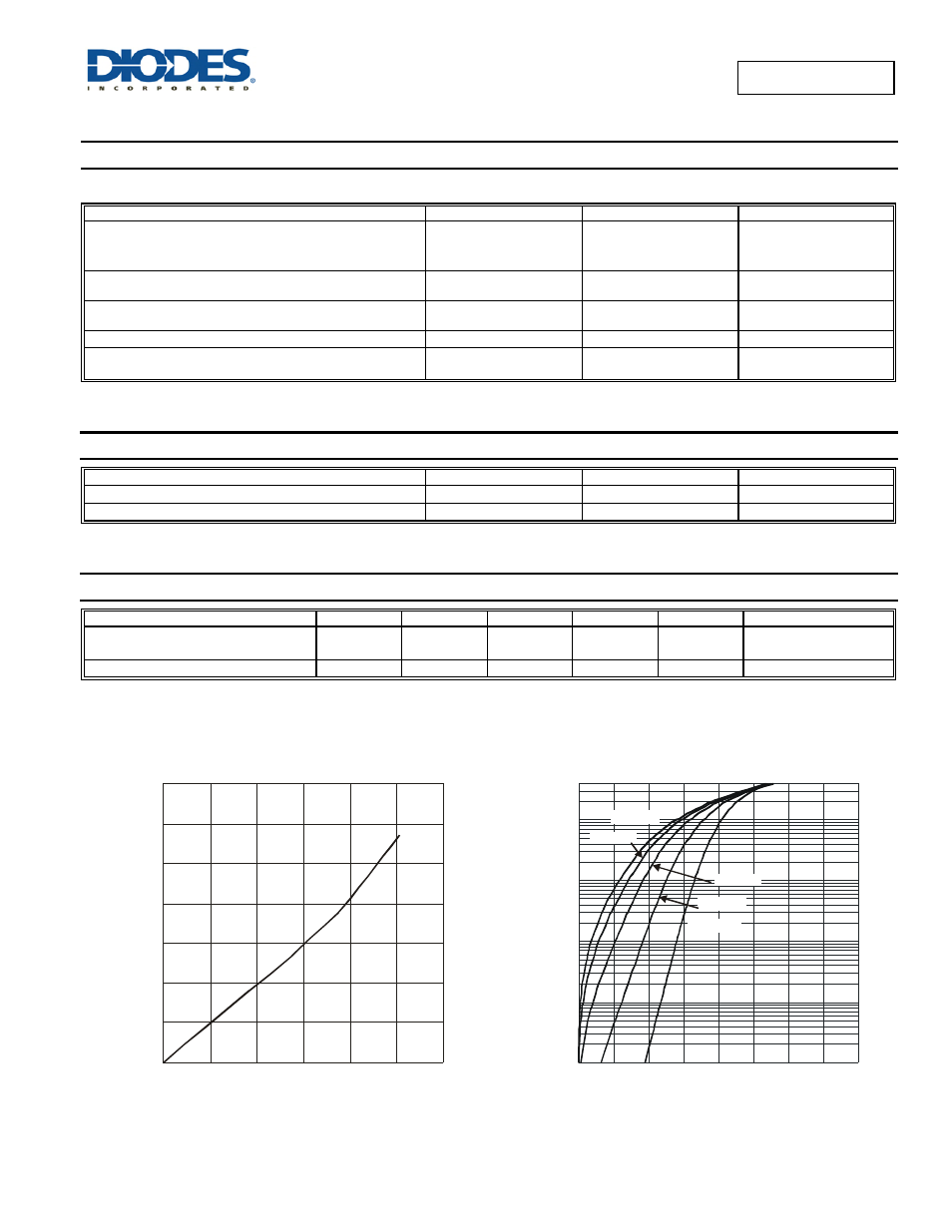
0
0.5
1.0
1.5
2.0
2.5
3.0
3.5
P
,
P
O
WE
R
DI
SSI
P
A
T
IO
N
(W
)
D
0
1
2
3
4
5
6
I
, AVERAGE FORWARD CURRENT (A)
F(AV)
Figure 1 Forward Power Dissipation
0.0001
0.001
0.01
0.1
1
0
100
200
300
400
500
600
700 800
Figure 2 Typical Forward Characteristics
V , INSTANTANEOUS FORWARD VOLTAGE (mV)
F
I
, INS
T
A
NT
A
NEOUS
F
O
RW
ARD
C
URRENT
(
A
)
F
T = 25°C
A
T = 125°C
A
T = 150°C
A
T = 85°C
A
T = -55°C
A