Sbr8u60p5 new prod uc t, Package outline dimensions, Suggested pad layout – Diodes SBR8U60P5 User Manual
Page 4
SBR and POWERDI are registered trademarks of Diodes Incorporated.
SBR8U60P5
Document number: DS31731 Rev. 8 - 2
4 of 5
April 2013
© Diodes Incorporated
SBR8U60P5
NEW PROD
UC
T
Notes:
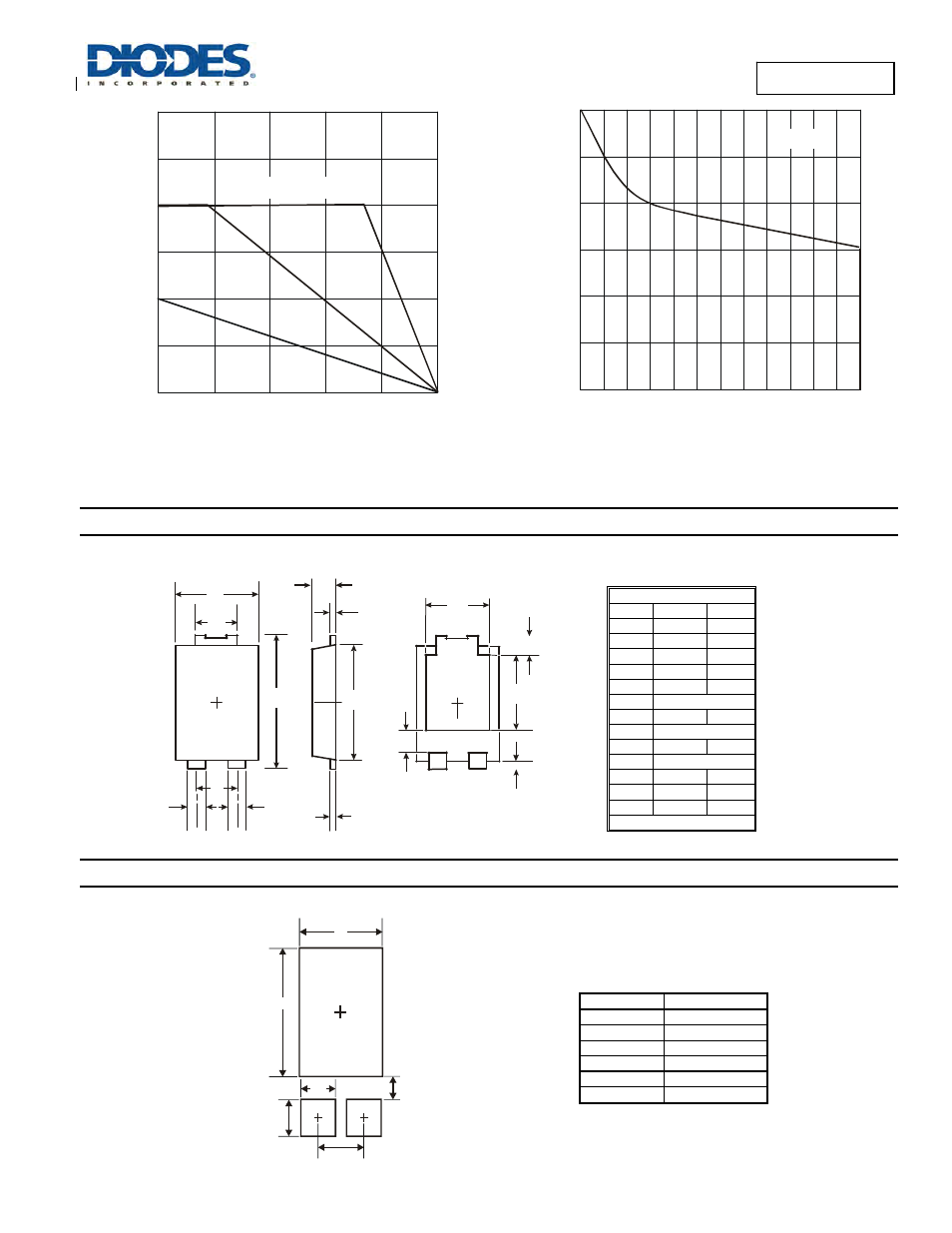
9. Device mounted on FR-4 substate, 2oz copper, with minimum recommended pad layout.
10. Device mounted on FR-4 substate, 2oz copper, with 10cm x 10cm pad layout.
Package Outline Dimensions
rsion.
Suggested Pad Layout
e latest version.
T , AMBIENT TEMPERATURE (°C)
A
Figure 7 DC Forward Current Derating Curve
I,
D
C
F
O
R
WA
R
D
C
U
R
R
ENT (
A
)
F
10
25
50
75
100
125
150
12
6
8
2
4
0
Note 10
Note 9
Based on Lead Temp (T )
L
V , DC REVERSE VOLTAGE (V)
R
Figure 8 Operating Temperature Derating
T
, D
E
R
A
T
E
D
AM
BI
E
N
T
T
EM
P
E
R
A
T
U
R
E (
°C
)
A
0
25
50
75
100
125
150
0
20
40
60
Note 9
POWERDI5
Dim
Min
Max
A
1.05
1.15
A2
0.33
0.43
b1
0.80
0.99
b2
1.70
1.88
D
3.90
4.05
D2
3.054 Typ
E
6.40
6.60
e
1.84 Typ
E1 5.30 5.45
E2 3.549
Typ
L 0.75
0.95
L1 0.50 0.65
W 1.10 1.41
All Dimensions in mm
Dimensions
Value (in mm)
C
1.840
G
0.852
X
3.360
X1
1.390
Y
4.860
Y1
1.400
E
E1
b1
A
A2
A2
D
b2
b1
e
D2
L
E2
L1
W
G
X
C
Y1
(2x)
Y
X1
(2x)