Sbr8u60p5 new prod uc t, Maximum ratings, Thermal characteristics – Diodes SBR8U60P5 User Manual
Page 2: Electrical characteristics
SBR and POWERDI are registered trademarks of Diodes Incorporated.
SBR8U60P5
Document number: DS31731 Rev. 8 - 2
2 of 5
April 2013
© Diodes Incorporated
SBR8U60P5
NEW PROD
UC
T
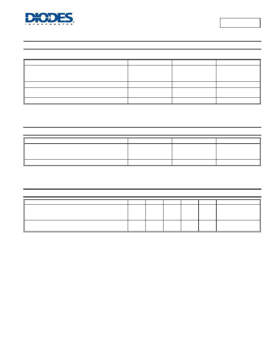
Maximum Ratings
(@T
A
= +25°C, unless otherwise specified.)
Single phase, half wave, 60Hz, resistive or inductive load.
For capacitance load, derate current by 20%.
Characteristic Symbol
Value
Unit
Peak Repetitive Reverse Voltage
Working Peak Reverse Voltage
DC Blocking Voltage
V
RRM
V
RWM
V
RM
60 V
Average Rectified Output Current
I
O
8 A
Non-Repetitive Peak Forward Surge Current 8.3ms
Single Half Sine-Wave Superimposed on Rated Load
I
FSM
280 A
Repetitive Peak Avalanche Power (1µs, +25°C)
P
ARM
5,000 W
Thermal Characteristics
Characteristic Symbol
Value
Unit
Maximum Thermal Resistance
Thermal Resistance Junction to Soldering (Note 6)
Thermal Resistance Junction to Ambient (Note 7)
R
θJS
R
θJA
3
60
°C/W
Operating and Storage Temperature Range
T
J
, T
STG
-65 to +150
°C
Electrical Characteristics
(@T
A
= +25°C, unless otherwise specified.)
Characteristic Symbol
Min
Typ
Max
Unit
Test
Condition
Forward Voltage Drop
V
F
—
—
—
0.30
0.46
—
0.35
0.53
0.5
V
I
F
= 1.0A, T
J
= +25°C
I
F
= 8A, T
J
= +25°C
I
F
= 8A, T
J
= +125°C
Leakage Current (Note 8)
I
R
—
—
0.12
—
0.6
100
mA
V
R
= 60V, T
J
= +25°C
V
R
= 60V, T
J
= +125°C
Notes:
6. Theoretical R
θJS
calculated from the top center of the die straight down to the PCB cathode tab solder junction.
7. Polymide PCB, 2 oz. Copper, minimum recommended pad layout pe8. Short duration pulse test used to minimize self-heating effect.