Electrical characteristics, Operational efficiency chart, Zlls410 – Diodes ZLLS410 User Manual
Page 3
ZLLS410
Document number: DS32080 Rev. 3 - 2
3 of 6
March 2012
© Diodes Incorporated
ZLLS410
Electrical Characteristics
@T
A
= 25°C unless otherwise specified
Characteristic Symbol
Min
Typ
Max
Unit
Test
Condition
Reverse Breakdown Voltage
V
(BR)R
10
−
−
V
I
R
= 200µA
Forward Voltage (Note 6)
V
F
−
−
−
285
350
500
300
380
580
mV
mV
mV
I
F
= 10mA
I
F
= 100mA
I
F
= 1A
Reverse Current
I
R
−
−
−
−
0.5
0.7
1
−
4
5
6
200
μA
μA
μA
μA
V
R
= 5V
V
R
= 8V
V
R
= 10V
V
R
= 8V, T
A
= 85°C
Diode Capacitance
C
D
−
37
−
pF
f = 1MHz, V
R
= 10V
Reverse Recovery Time
Reverse Recovery Charge
t
rr
Q
rr
−
−
3
210
−
−
ns
pC
Switched from I
F
= 500mA to V
R
= 5.5V
Measured @ I
R
= 50mA.
di/dt = 500mA/ns,
R
source
= 6
Ω; R
load
= 10
Ω
Notes:
6. Measured under pulsed conditions. Pulse width
≤ 300μs. Duty cycle < 2%
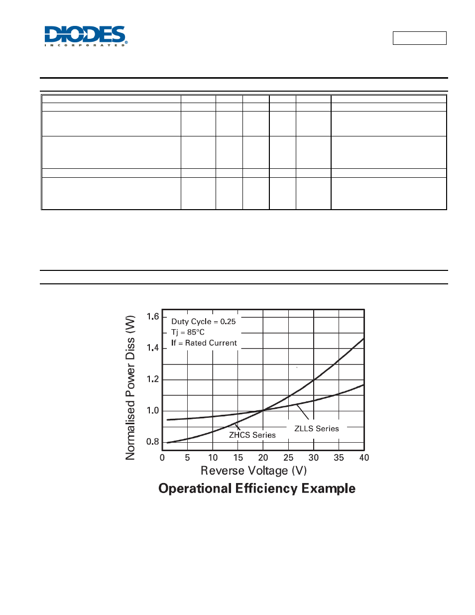
Operational efficiency chart
The operational efficiency chart indicates the beneficial use of the ZLLS series diodes in applications requiring higher voltage, higher temperature
operation. Circuits requiring low voltage low temperature operation will benefit from using Zetex low V
F
ZHCS series diodes.