Zlls1000, Maximum ratings, Thermal characteristics – Diodes ZLLS1000 User Manual
Page 2: Thermal characteristics and derating information, Derating curve, Transient thermal impedance
ZLLS1000
Document Number DS32021 Rev. 6 - 2
2 of 6
July 2012
© Diodes Incorporated
A Product Line of
Diodes Incorporated
ZLLS1000
Maximum Ratings
(@T
A
= +25°C, unless otherwise specified.)
Characteristic Symbol
Value
Unit
Continuous Reverse Voltage
V
R
40 V
Forward Current
I
F
1.16 A
Peak Repetitive Forward Current
Rectangular Pulse Duty Cycle 50% 100
μs pulse width
I
FPK
2.6 A
Non Repetitive Forward Current
t
≤100μs
t
≤10ms
I
FSM
22
6.4
A
A
Thermal Characteristics
Characteristic Symbol
Value
Unit
Power Dissipation @T
A
= +25°C
Single Die Continuous
Single Die Measured at t<5 secs
P
D
0.8
1.18
W
Thermal Resistance Junction to Ambient (Note 4)
R
θJA
155 °C/W
Thermal Resistance Junction to Ambient (Note 5)
R
θJA
106 °C/W
Thermal Resistance Junction to Lead (Solder Point)
R
θJL
80 °C/W
Storage temperature range
T
STG
-55 to +150
°C
Junction temperature
T
J
150 °C
Notes:
4. For a device surface mounted on 25mm x 25mm FR4 PCB with high coverage of single sided 1oz copper, in still air conditions.
5. For a device mounted on FRB PCB measured at t<5secs.
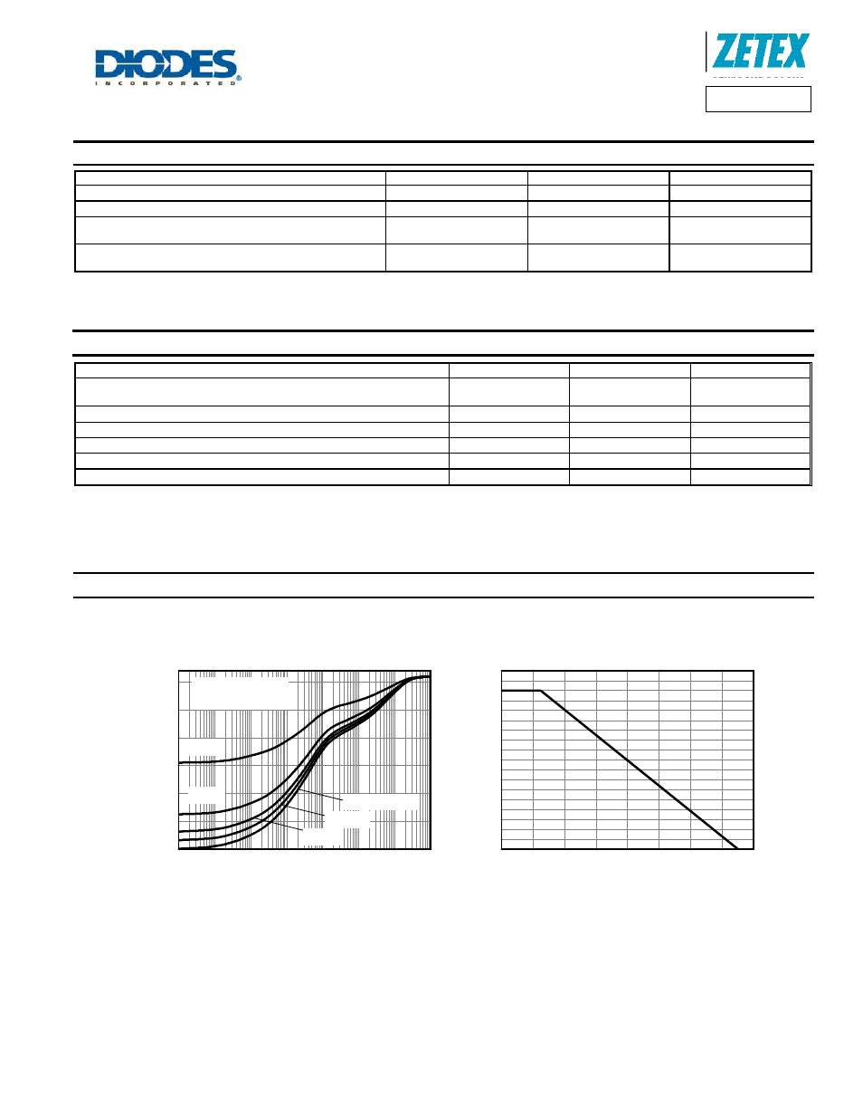
Thermal Characteristics and Derating information
0
20
40
60
80
100
120
140
160
0.0
0.1
0.2
0.3
0.4
0.5
0.6
0.7
0.8
0.9
Derating Curve
Temperature (°C)
M
a
x P
o
wer
Di
ssi
p
a
ti
on
(W
)
100µ
1m
10m 100m
1
10
100
1k
0
50
100
150
T
amb
=25°C
Rectangular Pulse
Transient Thermal Impedance
D=0.5
D=0.2
D=0.1
Single Pulse
D=0.05
T
h
e
rm
a
l R
e
si
st
a
n
ce
(°
C/
W)
Pulse Width (s)