Maximum ratings (per leg), Thermal characteristics (per leg), Electrical characteristics (per leg) – Diodes SBR20A120CTE User Manual
Page 2
SBR is a registered trademark of Diodes Incorporated.
SBR20A120CTE
Document number: DS35608 Rev. 3 - 2
2 of 4
September 2012
© Diodes Incorporated
SBR20A120CTE
NEW PROD
UC
T
Maximum Ratings (Per Leg)
(@T
A
= +25°C, unless otherwise specified.)
Single phase, half wave, 60Hz, resistive or inductive load.
For capacitance load, derate current by 20%.
Characteristic Symbol
Value
Unit
Peak Repetitive Reverse Voltage
Working Peak Reverse Voltage
DC Blocking Voltage
V
RRM
V
RWM
V
RM
120 V
Average Rectified Output Current Per Device
(Per Leg)
(Total)
I
O
10
20
A
Non-Repetitive Peak Forward Surge Current 8.3ms
Single Half Sine-Wave Superimposed on Rated Load
I
FSM
180 A
Thermal Characteristics (Per Leg)
Characteristic Symbol
Value
Unit
Maximum Thermal Resistance, Junction to Case
R
θJC
2 ºC/W
Operating and Storage Temperature Range
T
J
, T
STG
-65 to +150
ºC
Electrical Characteristics (Per Leg)
(@T
A
= +25°C, unless otherwise specified.)
Characteristic Symbol
Min
Typ
Max
Unit
Test
Condition
Forward Voltage Drop
V
F
-
-
0.75
0.62
0.79
0.65
V
I
F
= 10A, T
J
= +25ºC
I
F
= 10A, T
J
= +125ºC
Leakage Current (Note 6)
I
R
-
-
-
-
0.1
20
mA
V
R
= 120V, T
J
= +25ºC
V
R
= 120V, T
J
= +125ºC
Notes:
6. Short duration pulse test used to minimize self-heating effect.
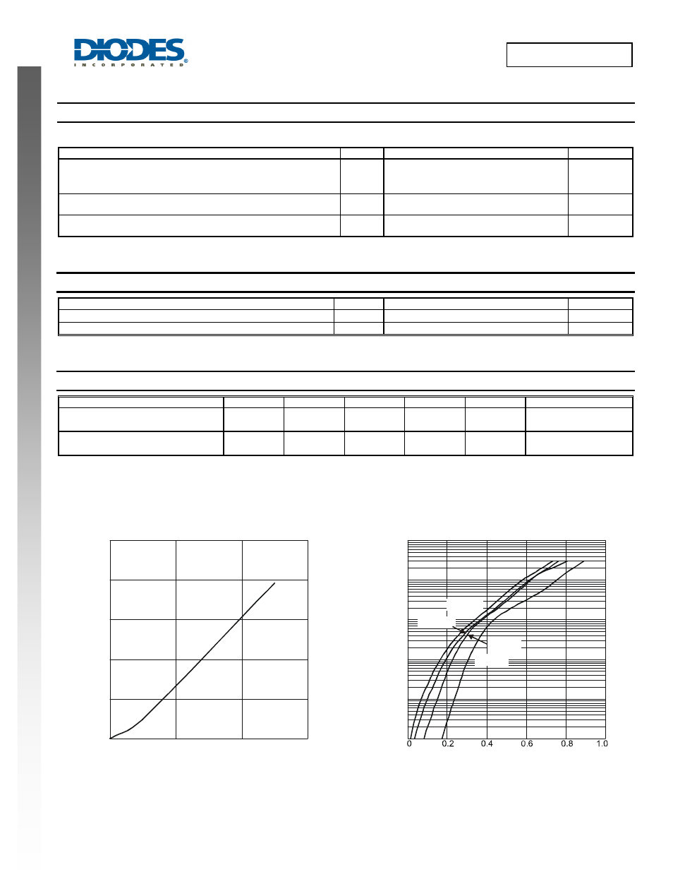
10
15
20
25
0
10
20
30
0
5
I
AVERAGE FORWARD CURRENT (A)
Fig. 1 Forward Power Dissipation
F(AV)
P
,
P
O
WE
R
DISS
IP
A
T
IO
N (
W
)
D
100,000
I
, I
N
ST
ANT
A
NEO
U
S
FO
RW
ARD C
U
RRENT (
m
A)
F
10,000
1,000
100
10
1
Fig. 2 Typical Forward Characteristics
V , INSTANTANEOUS FORWARD VOLTAGE (V)
F
T = 25°C
A
T = 85°C
A
T = 125°C
A
T = 150°C
A