Sbr1u30sv, Maximum ratings, Thermal characteristics – Diodes SBR1U30SV User Manual
Page 2: Electrical characteristics
SBR1U30SV
Document number: DS35028 Rev. 4 - 2
2 of 4
April 2013
© Diodes Incorporated
SBR1U30SV
SBR is a registered trademark of Diodes Incorporated.
Maximum Ratings
(@T
A
= +25°C, unless otherwise specified.)
Single phase, half wave, 60Hz, resistive or inductive load.
For capacitance load, derate current by 20%.
Characteristic Symbol
Value
Unit
Peak Repetitive Reverse Voltage
Working Peak Reverse Voltage
DC Blocking Voltage
V
RRM
V
RWM
V
RM
30 V
Average Rectified Output Current (See Figure 1)
I
O
1.0 A
Non-Repetitive Peak Forward Surge Current
I
FSM
2.5
A
Thermal Characteristics
Characteristic Symbol
Value
Unit
Thermal Resistance Junction to Ambient (Note 5)
R
θJA
130 °C/W
Operating and Storage Temperature Range
T
J
, T
STG
-65 to +150
°C
Electrical Characteristics
(@T
A
= +25°C, unless otherwise specified.)
Characteristic Symbol
Min
Typ
Max
Unit Test
Condition
Forward Voltage Drop
V
F
—
—
0.37
—
0.43
0.51
V
I
F
= 0.5A, T
J
= +25°C
I
F
= 1.0A, T
J
= +25°C
— 0.39 0.43
I
F
= 1.0A, T
J
= +125°C
Leakage Current (Note 6)
I
R
— 7 75 µA
V
R
= 5V, T
J
= +25°C
— 8 90 µA
V
R
= 12V, T
J
= +25°C
— 16 150 µA
V
R
= 30V, T
J
= +25°C
— 4 — mA
V
R
= 30V, T
J
= +125°C
Notes:
5. Device mounted on FR-4 substrate PC board, with minimum recommended pad layout
6. Short duration pulse test used to minimize self-heating effect.
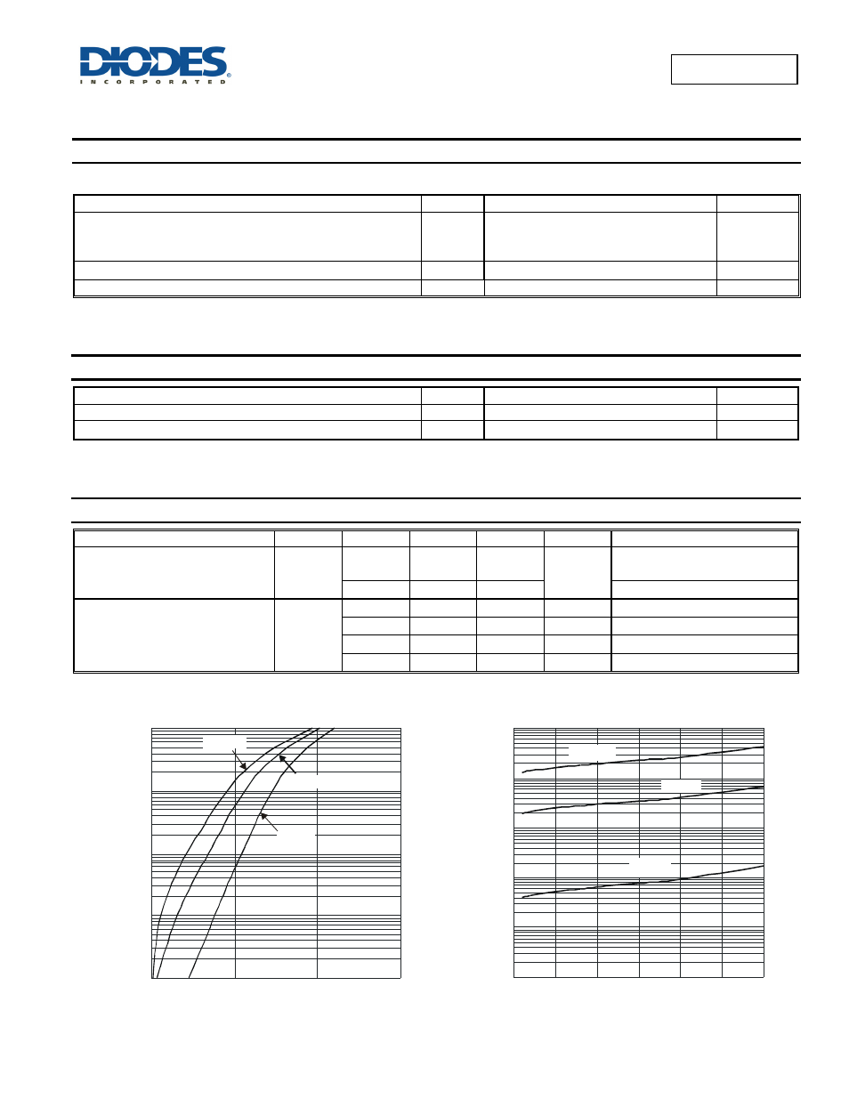
V , INSTANTANEOUS FORWARD VOLTAGE (V)
F
Figure 1 Typical Forward Characteristics
I,
I
N
S
TAN
TANE
O
U
S F
O
R
WA
R
D
C
U
R
R
EN
T
(m
A
)
F
0.0001
0.001
0.01
0.1
1
0
200
400
600
T =25°C
A
T =85°C
A
T =125°C
A
0
5
10
15
20
25
30
V , INSTANTANEOUS REVERSE VOLTAGE (V)
R
Figure 2 Typical Reverse Characteristics
I,
I
N
S
TAN
TAN
E
O
U
S
R
EV
E
R
SE
C
U
R
R
EN
T
(µ
A
)
R
0.1
1
10
100
1000
10000
T =125°C
A
T =25°C
A
T =85°C
A