New prod uc t, Maximum ratings, Thermal characteristics – Diodes SBR160S23 User Manual
Page 2: Electrical characteristics
SBR160S23
Document number: DS32269 Rev. 3 - 2
2 of 4
November 2010
© Diodes Incorporated
SBR160S23
SBR is a registered trademark of Diodes Incorporated.
NEW PROD
UC
T
Maximum Ratings
@T
A
= 25°C unless otherwise specified
Single phase, half wave, 60Hz, resistive or inductive load.
For capacitance load, derate current by 20%.
Characteristic Symbol
Value
Unit
Peak Repetitive Reverse Voltage
Working Peak Reverse Voltage
DC Blocking Voltage
V
RRM
V
RWM
V
RM
60 V
Average Rectified Output Current
I
O
900 mA
Average Peak Forward Current; D.C. = 50%
I
FAV
1600 mA
Non-Repetitive Peak Forward Surge Current
8.3ms Single Half Sine-Wave Superimposed on Rated Load
I
FSM
15 A
Thermal Characteristics
Characteristic Symbol
Value
Unit
Power Dissipation
P
D
500 mW
Typical Thermal Resistance
Thermal Resistance Junction to Ambient Air (Note 3)
Thermal Resistance Junction to Ambient Air (Note 4)
R
θJA
R
θJA
305
271
ºC/W
Operating and Storage Temperature Range
T
J
, T
STG
-65 to +150
ºC
Electrical Characteristics
@T
A
= 25°C unless otherwise specified
Characteristic Symbol
Min
Typ
Max
Unit
Test
Condition
Reverse Breakdown Voltage
V
R
60 - - V
IR = 300
μA
Forward Voltage (Per Diode)
V
F
-
-
-
-
-
470
530
600
740
mV
I
F
= 500mA
I
F
= 750mA
I
F
= 1000mA
I
F
= 1500mA
Leakage Current (Note 5)
I
R
- -
100
µA
V
R
= 45V, T
J
= 25ºC
Total Capacitance
C
T
- 19 -
pF
V
R
= 25V, f = 1MHz
Reverse Recovery Time
t
rr
- 16 -
ns
I
F
= I
R
= 10mA, IRR = 0.1*I
R
R
L
= 100
Ω
Notes:
3. Part mounted on FR-4 board with recommended pad layout, which can be found on our websit
4. Part mounted on Polymide board with recommended pad layout, which can be found on our website at
5. Short duration pulse test used to minimize self-heating effect.
0
0.05
0.10
0.15
0.20
0.25
0.30
0.35
0.40
0
0.2
0.4
0.6
0.8
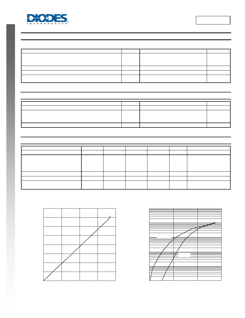
Fig. 1 Forward Power Dissipation
I
, AVERAGE FORWARD CURRENT (A)
F(AV)
P
,
P
O
WE
R
DI
SSI
P
A
T
IO
N
(W
)
D
0.0001
0.001
0.01
0.1
1
10
0
200
400
600
Fig. 2 Typical Forward Characteristics
V , INSTANTANEOUS FORWARD VOLTAGE (mV)
F
I
,
INST
ANT
A
NEOUS
F
O
R
W
A
RD CURR
ENT
(
A
)
F
T = 25°C
A
T = 125°C
A