Installation of h2s sensor, Procedure – Analytical Industries GPR-7500 AIS Trace PPM Hydrogen Sulfide Analyzer User Manual
Page 17
Advanced Instruments, Inc.
17
Note: The male and female power terminals snap together, making it difficult to detach them when
connecting the shield to the ground. However, after connecting the shield, ensure that the male terminal is
fully inserted and secured into the female terminal block.
Installation of H2S Sensor
The GPR-7500AIS Oxygen Transmitter is equipped with SS sensor housing. This housing offers ease of
replacement of sensor and at the same time prevents any leakage into the system. The sensor is screwed in
and makes the seal against the flat surface of the sensor housing with the integral O-
ring on the sensor’s
threaded front end. The integrity of the sensor and the sensor housing has been tested at the factory prior to
shipment and is fully operational from the shipping container.
Caution: DO NOT dissect the sensor. The sensor contains a corrosive liquid electrolyte that
could be harmful if touched or ingested, refer to the Material Safety Data Sheet contained in the
Owner’s Manual appendix. Avoid contact with any liquid or crystal type powder in or around the
sensor or sensor housing, as either could be a form of electrolyte. Leaking sensors should be disposed off in
a manner similar to that of a common battery in accordance with local regulations.
Should the transmitter come without sensor installed or need to install a new sensor, follow the guidelines
give below.
Procedure
1. Remove the two (2) clamps securing the right side
corners and open the door of the fiber glass enclosure.
2. Remove the PCB along with the ribbon cable from the
top of the sensor by gently pulling the connector on the
sensor PCB.
3. Remove the ribbon cable from the PCB by gently
pulling the two small levers on the side of the ribbon
cable connector (unlocking the ribbon cable).
4. Remove the PCB from the sensor by gently pulling it
off.
Avoid electrostatic discharge
– touch a metal surface with your bare hand before contacting
the PCB. Clean all surfaces with a damp cloth only
5. Turn the sensor anti clockwise until loosen and then pull it off the housing.
6. Remove the new sensor from the bag.
7. Screw the new sensor in to the sensor housing until finger tight.
8. Align 4 pins of the sensor PCB with 4 pins of the sensor and gently push the PCB on to the sensor until
it is firmly seated.
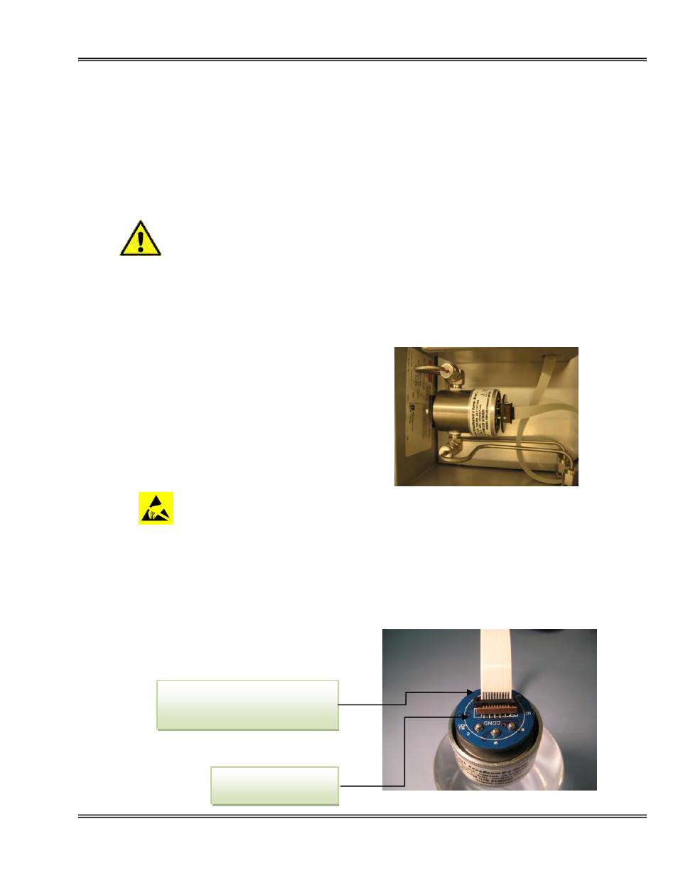
9. Insert the ribbon cable into the connector with bare conducting bars facing COND on the PCB and push
the two side levers on the connector (locking the
ribbon cable).
Sensor shown with ribbon cable half
inserted showing the conducting
bars facing COND on PCB
Levers on side of ribbon
cable connector