Gas connections, Procedure – Analytical Industries GPR-7500 AIS Trace PPM Hydrogen Sulfide Analyzer User Manual
Page 13
Advanced Instruments, Inc.
13
Gas Connections
The GPR-7500AIS with its standard flow through configuration is designed for positive pressure samples
and requires connections for an incoming sample and an outgoing vent line. Zero and span inlet ports are
offered as part of the optional sample systems. The user is responsible for calibration gases and other
required components, see below.
Procedure
Caution: Do not change the factory setting until instructed to do in this manual.
1. If analyzer has a sample inlet and a sample vent line, connect the sample to SAMPLE and vent to the
VENT line.
2. Regulate the sample pressure as described in
“Pressure and Flow” section above.
3. Connect a
¼” vent line to the compression fitting to be used for venting the SAMPLE.
4. Connect a
¼” sample line to the compression fitting to be used to bring SAMPLE gas to the analyzer.
5. If equipped with optional SPAN and/or ZERO ports, connect the SPAN and the ZERO gas lines to the
respective SPAN and ZERO ports of the analyzer
6. Set the SAMPLE, SPAN and the ZERO gas pressure between 5-30 psig, keep the sample, span and
zero gas pressure within 5 PSIG of each other for better gas flow control..
7. Select sample gas and allow it to flow through the transmitters and set the flow rate to1- 2 SCFH.
8. Note: If equipped with the optional coalescing filter, regulate the inlet pressure less than 30 psig.
9. Flow rates of 1-5 SCFH cause no appreciable change in the sample reading. However, flow rates above
5 SCFH may generate a backpressure on the sensor and cause erroneous sample readings due to the
fact that the smaller diameter of the integral sample system tubing cannot vent the sample gas quickly
at higher flow rates. If the analyzer is not equipped with an integral flow control valve, a flow control
metering valve with a flow indicator upstream of the sensor must be installed to control the sample flow
rate. A flow rate of 1-2 SCFH or 0.5-1 L/min (liter per minute) is recommended for optimum
performance.
Caution: Do not place your finger over the vent (it pressurizes the sensor) to test the flow
indicator when gas is flowing to the sensor. Removing your finger (the restriction) generates a
sudden vacuum on the sensor and may lead to electrolyte leakage thus causing damage to the
sensor (will void sensor warranty).
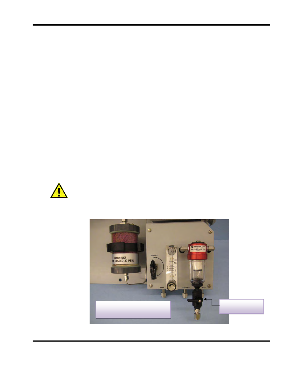
Sample system shown with optional
coalescing filter and H2S scrubber
Coalescing filter
drain valve