36 chapter 1: product introduction, P5ql-em usb 2.0 connectors, P5ql-em intrusion connector – Asus P5QL-EM User Manual
Page 48: Chassis
1-36
Chapter 1: Product introduction
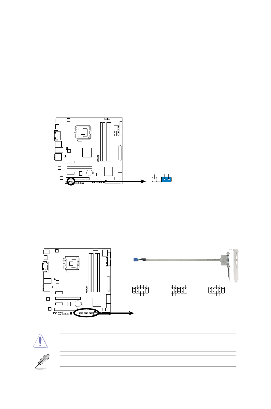
10. USB connectors (10-1 pin USB1112, USB910, USB78)
Never connect a 1394 cable to the USB connectors. Doing so will damage the
motherboard!
The USB module is purchased separately.
9. Chassis intrusion connector (4-1 pin CHASSIS)
This connector is for a chassis-mounted intrusion detection sensor or switch.
Connect one end of the chassis intrusion sensor or switch cable to this
connector. The chassis intrusion sensor or switch sends a high-level signal to
this connector when a chassis component is removed or replaced. The signal
is then generated as a chassis intrusion event.
By default, the pins labeled “Chassis Signal” and “Ground” are shorted with
a jumper cap. Remove the jumper caps only when you intend to use the
chassis intrusion detection feature.
P5QL-EM
R
P5QL-EM USB 2.0 Connectors
USB78
USB+5V USB_P8
-
USB_P8
+
GN
D
NC
USB+5V USB_P7
-
USB_P7
+
GN
D
1
USB910
USB+5V USB_P10- USB_P10+ GN
D
NC
USB+5V USB_P9- USB_P9+
GND
1
USB1112
USB+5V USB_P12- USB_P12+ GN
D
NC
USB+5V USB_P1
1-
USB_P1
1+
GND
1
P5QL-EM Intrusion Connector
P5QL-EM
R
CHASSIS
+5VSB_MB
Chassis Signal GN
D
(Default)