2 motherboard layout, 2 chapter 2: hardware information, Pci1 – Asus P4PE User Manual
Page 28: Pci2 pci3 pci4 pci5 bluemagic pci slot, P4pe, Super i/o
2-2
Chapter 2: Hardware information
2.2
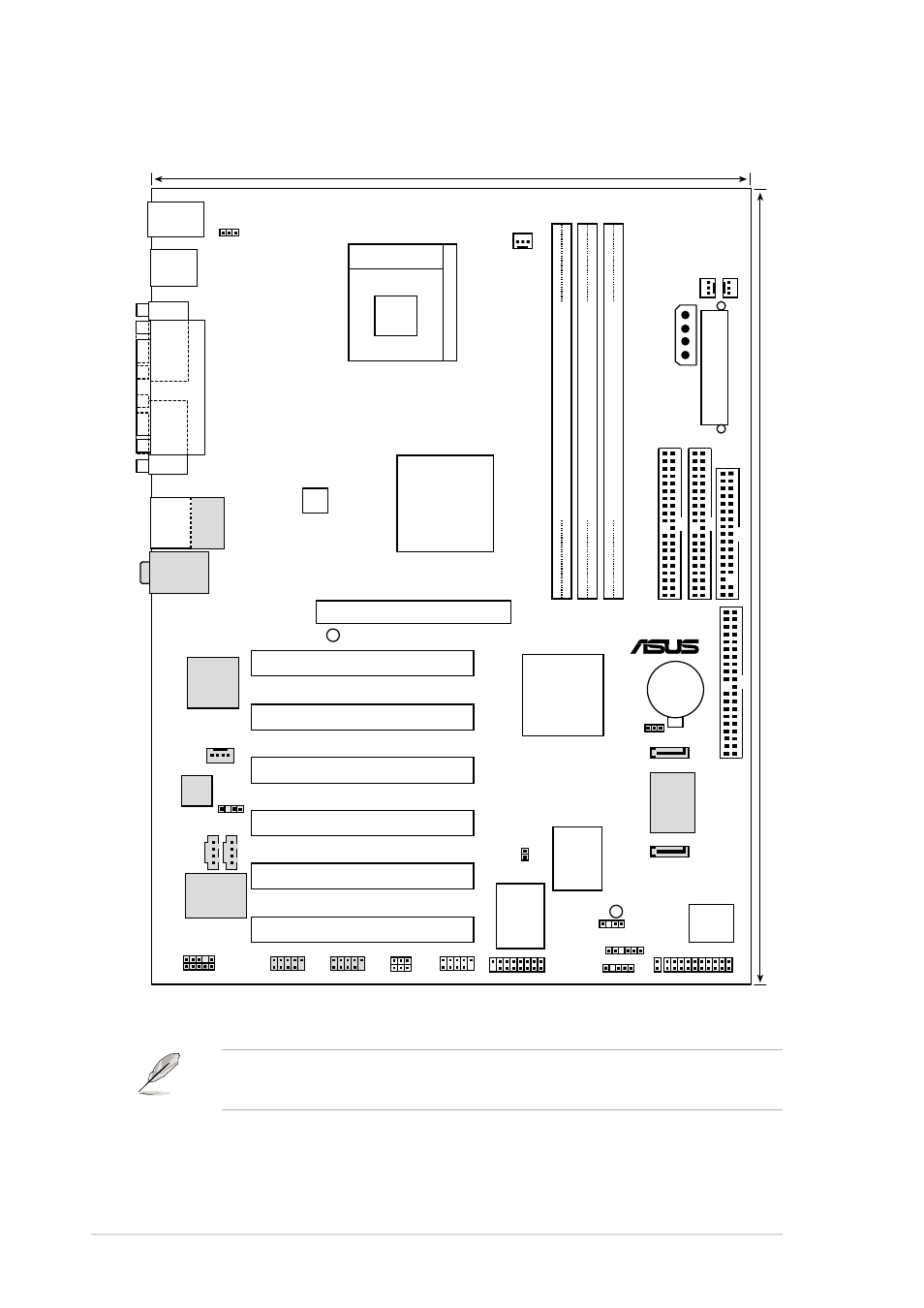
Motherboard layout
The audio, Serial ATA, IEEE 1394, and LAN features are optional.
These components are grayed out in the above motherboard layout.
22.86cm (9.0in)
30.5cm (12.0in)
PCI1
PANEL1
FLOPPY1
PRI_IDE
Intel I/O
Controller
Hub
(ICH4)
P4PE
®
ATX12V1
TRPWR1
COM1
P
ARALLEL
PORT
COM2
Socket 478
Intel 845PE
Memory
Controller
Hub (MCH)
SB_PWR1
CD1
AUX1
MODEM
EZ_PLUG1
WPCI_USB
FP_AUDIO1
IDE_LED1
Accelerated Graphics Port (AGP)
AGP_WARN1
GAME1
CLRTC1
SPDIF1
KBPWR1
CHASSIS1
USB_56
Super
I/O
4Mbit
Firmware
Hub
ASUS
ASIC
with
Hardware
Monitor
DDR DIMM1 (64/72 bit, 184-pin module)
0 1
PS/2KBMS
T: Mouse
B: Keyboard
DDR DIMM2 (64/72 bit, 184-pin module)
2 3
DDR DIMM3 (64/72 bit, 184-pin module)
4 5
Below:Mic In
Center:Line Out
Top:Line In
CPU_FAN1
SEC_IDE
CHA_F
AN1
PWR_F
AN1
PCI2
PCI3
PCI4
PCI5
BlueMagic PCI Slot
CR2032 3V
Lithium Cell
CMOS Power
A
T
X Power Connector
USB2.0
T: USB4
B: USB3
SMB1
USB2.0
T:USB1
B:USB2
Top:
RJ-45
SEC_SATA
PRI_SATA
PRI_RAID1
PROMISE
S
ATA
Controller
Audio
Codec
BroadCom
Gbit/Fast
BCM5702/4401
Ethernet
IEEE1394_2
IEEE1394_1
IR1
VIA
VT6307
Chipset